CHAPTER 3 - INSTALLATIONANDCONNECTION
For wiring distances longer than 50 m (150 ft), it is necessary to use
galvanic isolators for the XC1:11 to
Relays, contactors, solenoids or electromagnetic braking coils installed
near inverters can generate interference in the control circuit. In order to
eliminate this interference, connect RC suppressors in parallel with the
coils of AC relays. Connect a free - wheeling diode in case of DC relays/
When an external keypad (HMI) is used (Refer to chapter 8), separate the
cablethat connects the keypad totheinverter from other cables,maintaining
a minimum distance of 10 cm (4 in) between them.
– Keypad Start/Stop (Local Mode)
, you can operate the inverter in the local
mode. This operation mode is recommended for users who are operating the
inverter for the first time; without additional control connections. For start-up
according to this operation mode, follow chapter 5.
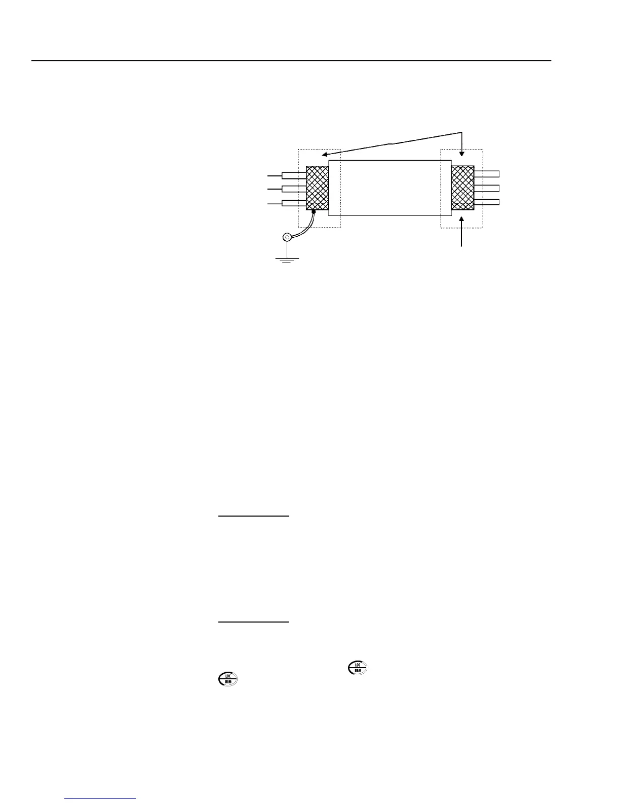
Connect the shield as shown in figure 3.14.
Screw located on the CC9 Board and on support plate of the CC9 Board
2-Wire Control Start/Stop (Remote Mode)
and inverter operating in
the factory default programming, the selection of the operation mode (Local/
Remote) is made via the key (default is Local).