EasyManua.ls Logo

WEG CFW-09 - Page 64

WEG CFW-09
362 pages
Print Icon
To Next Page IconTo Next Page
To Previous Page IconTo Previous Page
Loading...
65
CHAPTER 3 - INSTALLATIONANDCONNECTION
Figure 3.15
- XC1 (CC9)
w
iring for connection 2
Connection 3
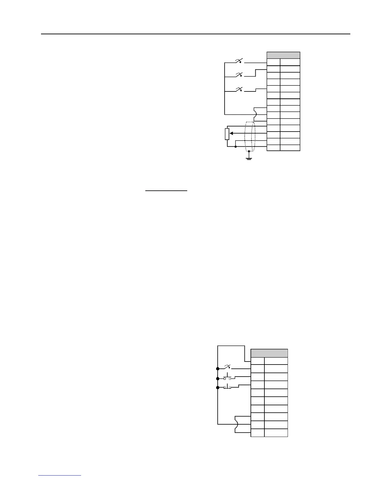
- 3-Wire Control Start/Stop
Selection of function Start/Stop with 3 wire control.
Parameters to be programmed:
Set DI3 to START
P265 = 14
Set DI4 to STOP
P266 = 14
Program P224 = 1 (DIx) if you want the 3 wire control in local mode.
Program P227 = 1 (DIx) if you want the 3 wire control in remote mode.
To program the rotationselection via DI2
Set P223 = 4
if in Local Mode
or
Set P226 = 4
if in Remote Mode.
S1 and S2 are
momentary push buttons,
NO contact for Start and NC contact
for Stop.
The speed reference can be viaAnalog InputAI (as in
Connection 2),
via
keypad
(HMI) (as in Connection 1),
or via any other source. The function Start/Stop is
described in
chapter
6 in this manual.
C
onnector XC1
1
DI1
2
DI2
3
DI3
4
DI4
5
DI5
6
DI6
7
COM
8
COM
9
24 Vdc
10
GND
11
+REF
12
AI1 +
13
AI1 -
14
- REF
Start/Stop
FWD/REV
JOG
CCW
CW
5 k
Figure 3.16
- XC1 (CC9) wiring for connection 3
Connector XC1
1
DI1
2
DI2
3
DI3
4
DI4
5
DI5
6
DI6
7
COM
8
COM
9
24 Vdc
10
GND
Start
FWD/REV
Stop

Table of Contents

Other manuals for WEG CFW-09

Related product manuals