CHAPTER 8 - CFW-09 OPTIONS AND ACCESSORIES
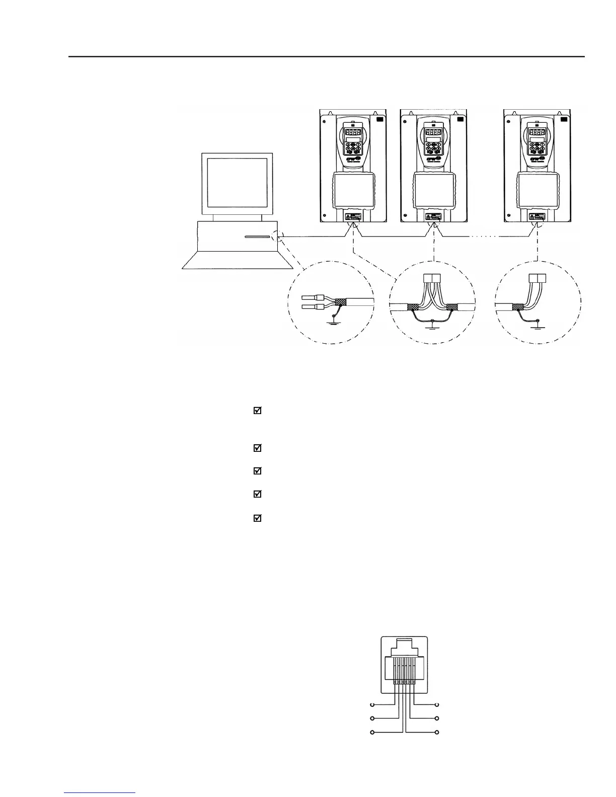
LINE TERMINATION: include line termination (120
S3.1/S3.2 (EBA) and S7.1/S7.2 (EBB) to “ON” (refer to items 8.1.1 and
GROUNDING OF THE CABLE SHIELD: connect the shielding to the
equipment frame (suitable grounding);
RECOMMENDED CABLE: for balanced shielding.
The RS-485 wiring must be laid separately from the power and control
The reference signal for the RS-485 interface (SREF) shall be used when
the network master is not connected to the system/installation ground.
For instance, if the master is powered from an isolated power supply it is
necessary to ground the power supply reference or carry this reference
signal to the whole system.
In general, it is possible to connect only signals A (-) and B (+), without
connecting the signal SREF.
RS-232 Serial Interface Module
TheRS-232interface isavailablefor theCFW-09throughthe modulepresented
CFW-09 network connection through RS-485 Serial Interface
- Description of the XC7 (RJ12) connector
8.13.7 Physical Connection