EasyManuals Logo

WEG CFW-09 User Manual

WEG CFW-09
362 pages
To Next Page IconTo Next Page
To Previous Page IconTo Previous Page
Page #306 background imageLoading...
Page #306 background image
307
CHAPTER 8 - CFW-09 OPTIONS AND ACCESSORIES
Reading of output current from the inverter at address 10
(supposing that the same was at 7.8A at the moment of the enquiry).
1) Master:
EOT
J
0 1
8
0
3 ENQ
Code P003
addr. 10
2) Inverter:
J STX 0
1
8 0 3 = 0H 0H 4H EH ETX
BCC
Code P003
P003 = 4EH =
78
= 7.8 A
10
addr.
10
8.13.5
Variables and Errors
of the Serial
Communication
8.13.5.1
Basic Variables
V00 (code 00800):
Indication of the inverter type (reading variable).
The reading of this variable allows the inverter type identification. For
the CFW-09 this value is 8, as defined in 8.13.3.7.
V02 (code 00802):
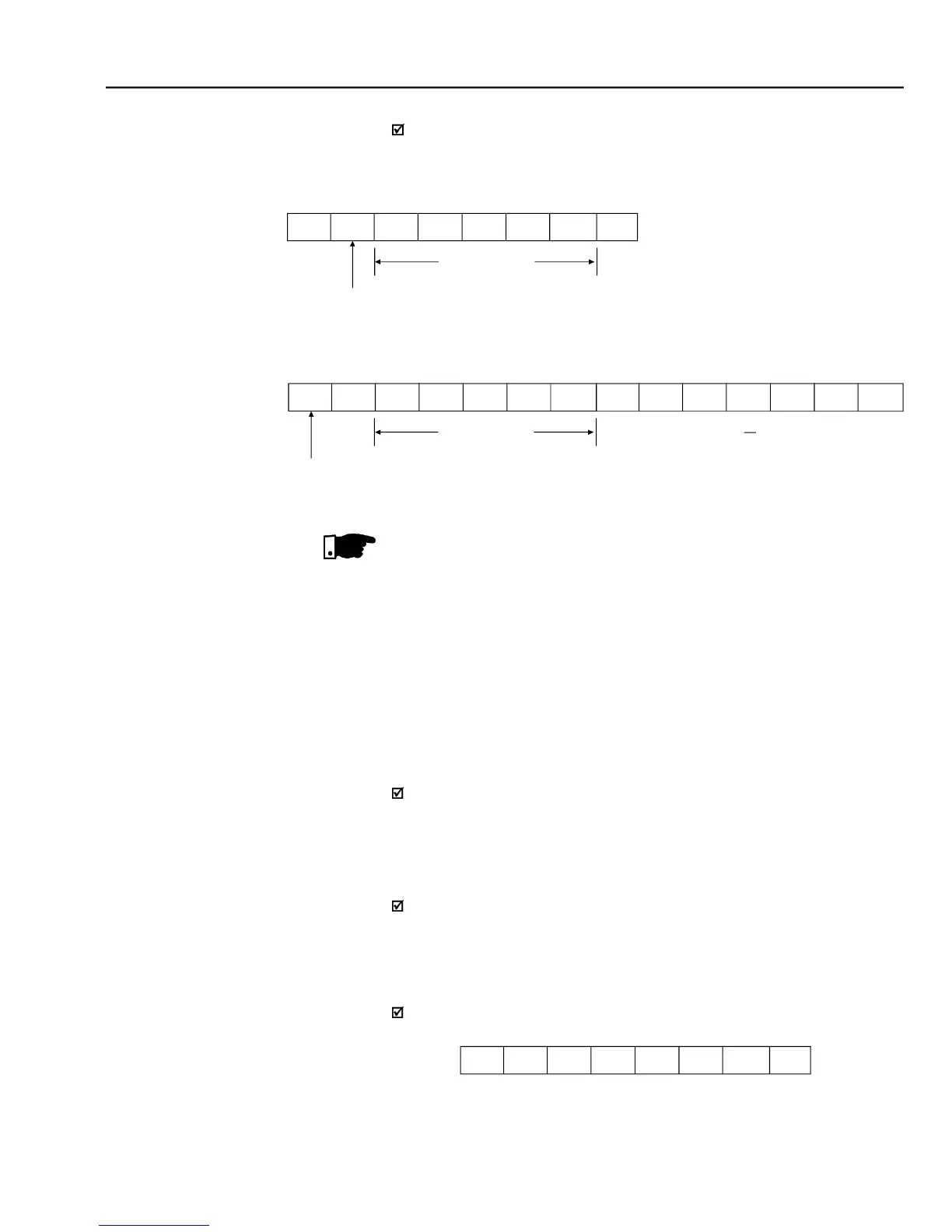
Indication of the inverter state (readingvariable).
- Logical status (byte-high)
- Error code (byte-low)
Where:
Logical status:
EL15 EL14 EL13 EL12 EL11 EL10 EL9 EL8
NOTE!
Values sent and received via serial interface are always integer values. It
is necessary to know the parameter resolution in order to read the correct
value. Ex. Real Current Value = 7.8 A

Received Value = 78.

Table of Contents

Other manuals for WEG CFW-09

Questions and Answers:

Question and Answer IconNeed help?

Do you have a question about the WEG CFW-09 and is the answer not in the manual?

WEG CFW-09 Specifications

General IconGeneral
Protection DegreeIP20
Cooling MethodForced ventilation
Power Range0.18 to 11 kW (0.25 to 15 HP)
Frequency Range0 to 400 Hz
Overload Capacity150% for 60 seconds
BrakingDC braking
CommunicationRS485, Modbus RTU
Output Voltage0 to input voltage
Control TypeV/F

Related product manuals