CHAPTER 3 - INSTALLATIONANDCONNECTION
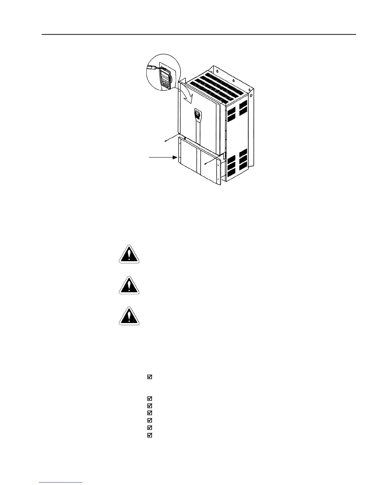
– Keypad (HMI) and cover removal procedure
The information below will be a guide to achieve a proper installation. Follow
also all applicable local standards for electrical installations.
Be sure that the AC input power is disconnected before making any terminal
The CFW-09 frequency inverter cannot be used as an emergency stop device.
Provide another devices for this function.
The power connection terminals can be of different sizes and configurations,
depending on the inverter model as shown in figure 3.6.
R, S, T: AC supply line. Models up to 10 A at 220-230 V can be operated
with two phases (single-phase operation) without current derating. In this
case the AC supply can be connected to any 2 of the 3 input terminals.
U, V, W: Motor connection.
-UD: Negative pole of the DC Link circuit.
BR: Dynamic Braking resistor connection.
+UD: Positive pole of the DC Link circuit.
DCR: Connection to the external DC Link choke (optional).