CHAPTER 7 - DIAGNOSTICS AND TROUBLESHOOTING
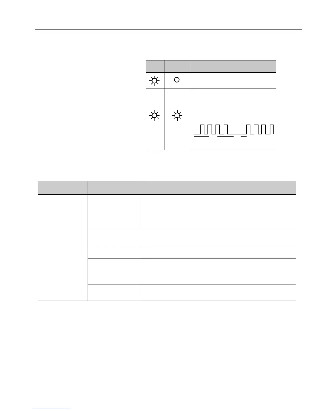
Inverter is powered up and is ready
A fault has been detected.
The FAULT LED flashes, indicating the number
If the fault E00 occurs, the ERROR
Check the power and control connections. For example the digital inputs DIX
programmed for Start/Stop, General Enable and No External Fault must be
connected to +24 V. For factory default programming, XC1:1 (DI1) must be
connected to +24 V(XC1:9) and XC1:10 connected to XC1:8.
Check if the external signal is properly connected.
Check the status of the speed potentiometer (if used).
Check if the parameters are properly programmed for the application.
Check if the inverter is not disabled due to a Fault condition (Refer to table
Check if there is a short-circuit between terminals XC1:9 and
circuit at 24 Vdc power supply).
Increase P169/P170 or P136/P137.
Indication of the inverter status LEDs: