CHAPTER 8 - CFW-09 OPTIONS AND ACCESSORIES
The CFW-09 provides an electronic thermal protectionforthe braking resistor
toavoidoverheating.Thebrakingresistorandthetransistorcanbedamagedif:
They are not properly sized;
Parameters P153, P154 and P155 are not properly set;
The line voltageexceeds the maximum allowed value.
The electronic thermal protection provided by the inverter, if properly
programmed, protects theDBresistor incaseof overloads notexpected during
normal operation, but it does not ensure protection in case of a dynamic
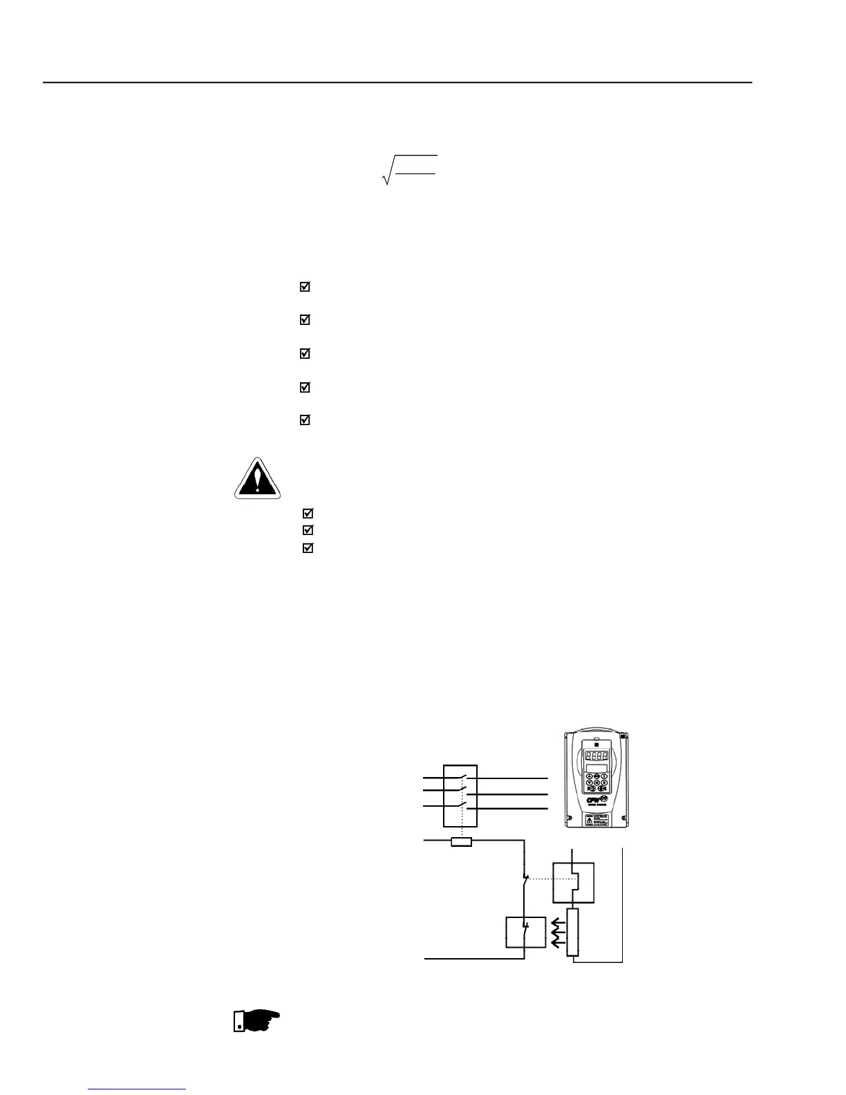
In this case the only guaranteed method to avoid burning the resistor and
eliminate risk of fire is the installation of a thermal overload relayin series with
the resistor and/or the installation of a thermostat on the resistor body, wiring
it in a wayto disconnect the inverter power supply is case of overheating, as
Connect the braking resistor between the +UD and BR power terminals
Make this connection with a twisted pair. Run this cable separately from
any signal or control wire;
Size the cable cross section according to the application, considering
If the braking resistor is installed inside the inverter panel, consider the
heat dissipated by the resistor when defining the panel ventilation;
to the Ohms value of the DB resistor and Parameter
to the resistor power rating in kW.
– Braking resistor connection
The maximum current can be determined by:
= Value set at P153 [V] / Resistor Ohms
The RMS braking current can be calculated by
corresponds to the sum of the braking
times during the most severe 5 minute cycle.
are the maximum peak and rated powers that the braking
chopper can deliver. The resistor power must be sized according to the
application braking duty cycle.
Through the power contacts of the bimetallic overload relay
Current during the DC-Braking process.


 To Next Page