CHAPTER 3 - INSTALLATIONANDCONNECTION
The inverter is provided withelectronic protection against motor overload.
This protection must be set according the specific motor. When the same
inverter drives several motors,use individual overload relaysfor each
motor. Maintain the electrical continuity of the motor cable shield.
If a disconnect switch or a contactor is inserted in the motor supply line,
DO NOT operate the disconnect switch with the motor running or when
is enabled. Maintain the electrical continuity of the motor cable
With the Dynamic Braking (DB) option, the DB resistor shall be mounted
externally. Figure 8.22 shows how to connect the DB resistor. Size it
according to the application, not exceeding the maximum current of the
Use twisted cable for the connection between inverter
Provide physical separation between this cable and the
cables. When the DB resistor is mounted inside the
watt loss generated when the enclosure size and
Inverters must be grounded for safety purposes (PE). The earth or ground
connection must complywiththe localregulations.For groundinguse
with cross section as indicated in table 3.5. Make the ground
toa grounding baror to thegeneralgroundingpoint (resistance
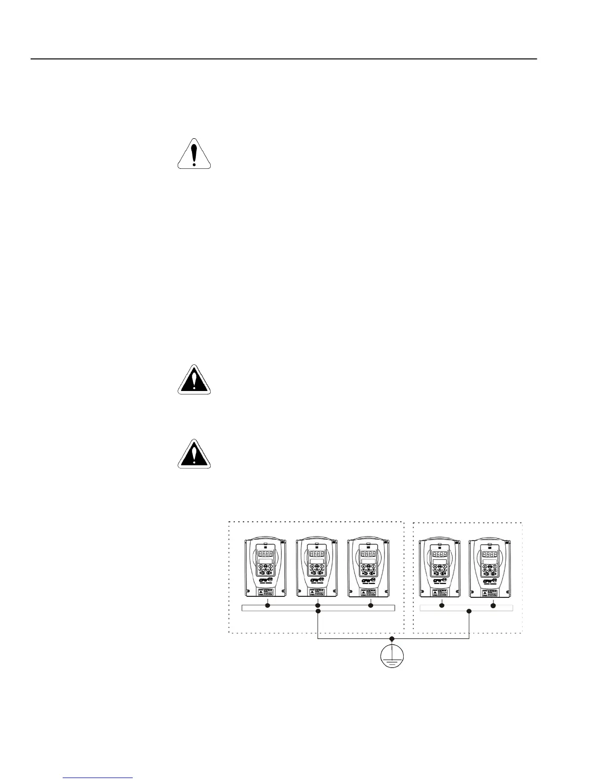
Do not share the ground wiring with other equipment that operates with
high current (for instance, high voltage motors, welding
several inverters are used together, refer to figure 3.10.
- Grounding connections for more than one inverter