CHAPTER 8 - CFW-09 OPTIONS AND ACCESSORIES
The Modbus protocol has beenalreadydeveloped 1979 firstly. Currentlyit is a
wide diffused open protocol, used by several manufacturers in different
equipment. The Modbus-RTU communication of the do CFW-09 has been
developed by considering two documents:
MODBUS Protocol Reference Guide Rev. J, MODICON, June 1996.
MODBUSApplication ProtocolSpecification,MODBUS.ORG, may8
In these documents are defined the format of the messages used by these
elements that are part of the Modbus network, the services (or functions) that
can be made available via network, and also how these elements exchange
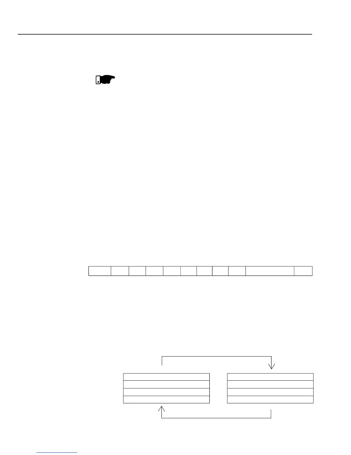
In the RTU mode each transmitted word has 1 start bit, eight data bits, 1
parity bit (optional) and 1 stop bit (2 stop bits, if parity bit is not used). Thus
the bit sequence for the transmission is as follows:
Two transmission modes aredefined in theprotocol definition:ASCIIand RTU.
The transmission modes define the form how the message bytes are
transmitted. It is not permitted to use the two transmission modes on the
In the RTU mode each transmitted word has one start bit, eight data bits, 1
paritybit (optional) and 1 stop bit (2 stop bits, if no paritybit is used). Thus the
bit sequence for the transmission of 1 byte is as follows:
The RS-232wiring must be laid separately from the power and control cables
You cannot use simultaneously the RS-232 and the RS-485 interface.
TheModbus RTU network operates in Master-Slavesystem andit can consist
of up to 247 slaves but only one Master. The master always initiates the
communication with a question toa slave andthe slave answers the question.
Both messages (question and answer) have the same structure: Address,
Function Code and CRC. Depending on what is being requested, only the
data field has variable length.