This chapter describes the CFW-09operation via thestandard Keypador
Human-Machine Interface(HMI), providingthe following information:
General Keypad Description;
Description of the Status Indicators.
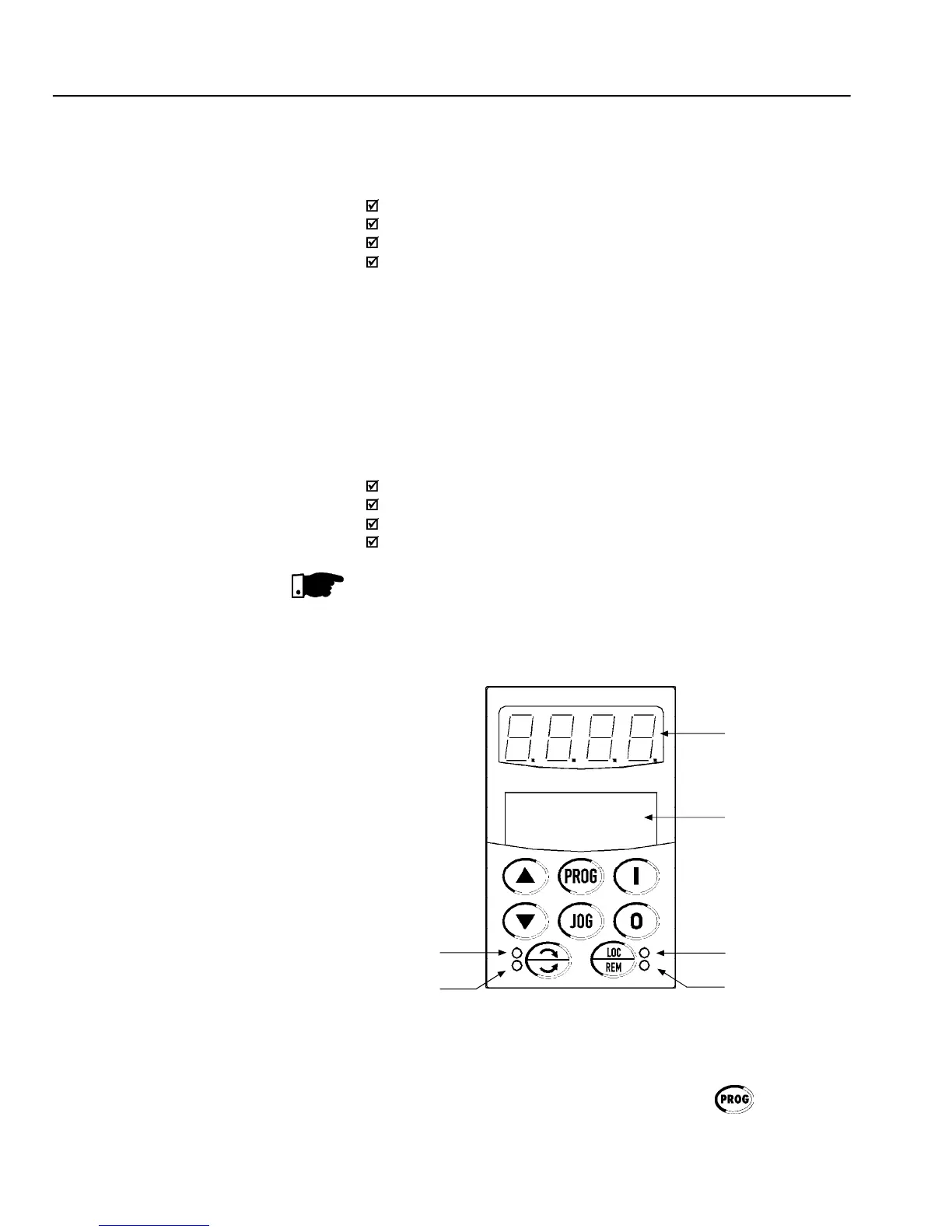
The standard CFW-09 Keypad has two readout displays: a LED readout
with a 4 digit,seven-segment displayand a LCD displaywith two lines of
16alphanumeric characters. There are also 4 indicator LEDs and 8 keys.
Figure 4.1 shows the front view of the Keypad and indicates the position
of the readouts, keys and status LEDs.
Functions of the LED Display:
The LED Display shows the fault codes, inverter status, the parameter
number and its value. For units of current, voltage or frequency, the LED
display shows the unit in the right side digit (L.S.D.) as shown here.
speed and other parameters
Whenthe indication is higher than 9999(for instance in rpm) the number
corresponding to the ten of thousand will not be displayed (ex.: 12345
rpm will be read as 2345 rpm). The correct indication will be displayed
Functions of the LCD Display:
The LCD Display shows the parameter number and its value
simultaneously, without requiring the toggling of the
provides a brief description of each parameter function, fault code and