CHAPTER 8 - CFW-09 OPTIONS AND ACCESSORIES
Whentheboard EBC1 isused, theselectedencoder should have thefollowing
Power Supply Voltage: 5 V to 15 V;
2 quadrature channels (90º) with complementaryoutputs (differential):
- “Linedriver” or “Push-Pull” output circuit type (with identical level as the
Electronic circuit isolated from the encoder frame;
Recommended number of pulseper revolution: 1024 ppr.
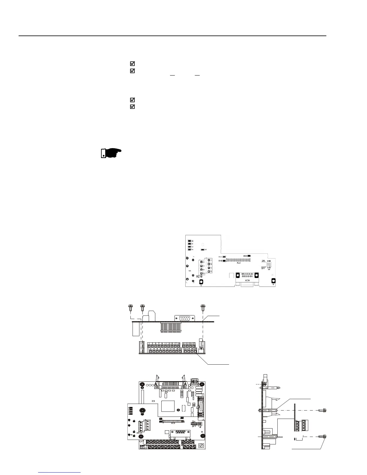
INSTALLATION OF THE EBC BOARD
The EBC board is installed directly on the control board CC9, fixed by means
of spacers and connected through the XC3 connector.
For installation in the models of size 1, remove the lateral plastic cover of the
Insert carefullythe pins of the connector XC3 (EBC1) into the female
connector XC3 of the control board CC9. Check if all pins of the connector
Press on the board center (near to XC3) until the connector is inserted
Fix the board to the 2 metallic spacers by means of the 2 bolts.
EBC1 board installation procedures