CHAPTER 8 - CFW-09 OPTIONS AND ACCESSORIES
For mounting the encoder on the motor, follow the recommendations below:
Couple the encoder directly to the motor shaft (use a flexible coupling
without torsional flexibility);
Both the shaft and the metallic frame of the encoder must be electrically
isolated from the motor. (min. spacing: 3 mm (0.119 in));
Use high quality flexible couplings to prevent mechanical oscillation or
The electrical connection must be made with shielded cable, maintaining a
minimum distance of about 254 mm (10 in) from other wiring (power, control
cables, etc.). If possible, install the encoder cable in a metallic conduit.
At start-up, program Parameter
- type of control - = 4 (vector with
encoder) to operate the motor with speed feedback through incremental
encoder. For more details about Vector Control operation, refer to chapter 5.
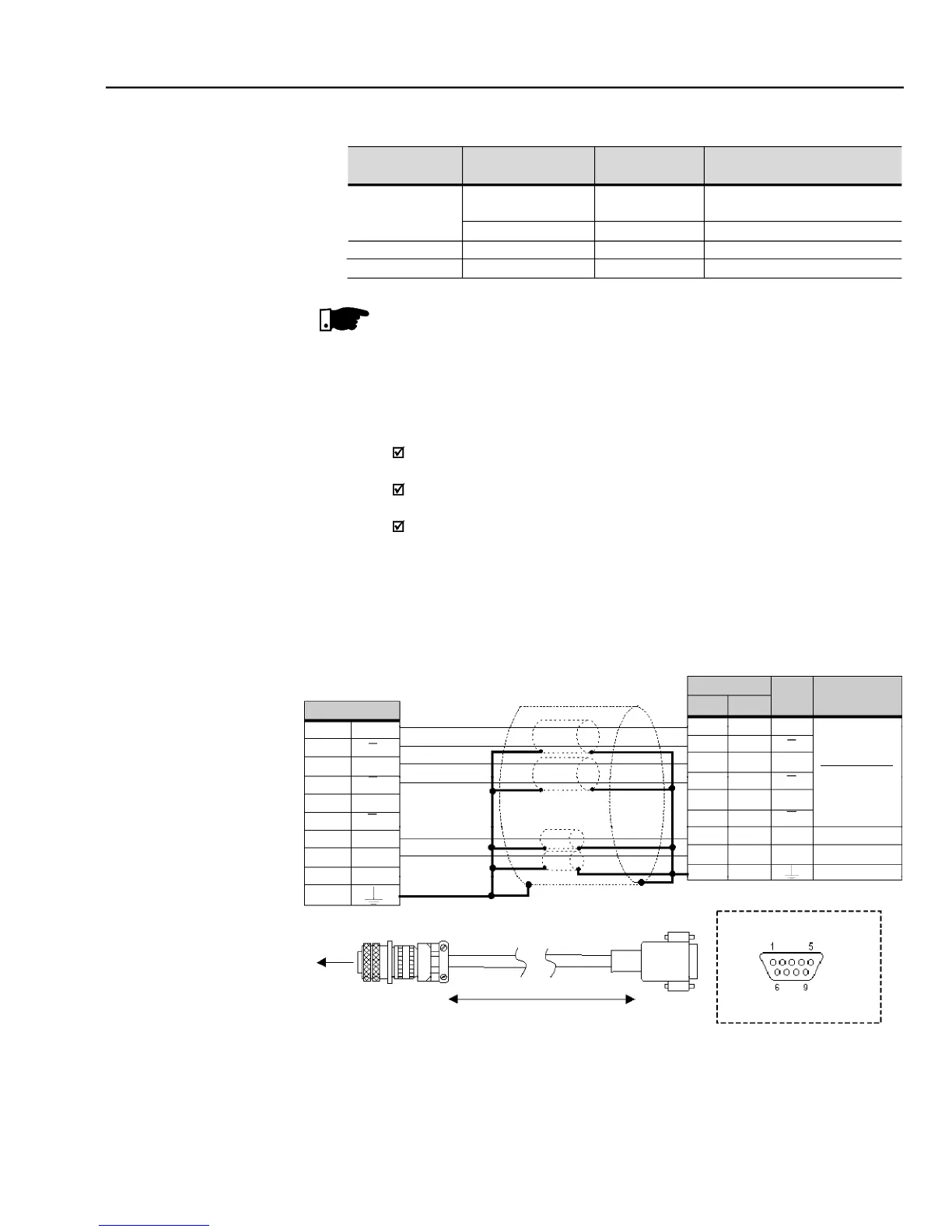
Connector XC9 (DB9 - Male)
External Power Supply Voltage for encoder: 5 to 15 Vdc, consumption = 40 mA plus consumption of the
0 V reference of the Power Supply Voltage.
Valid pin position with encoder HS35B models from Dynapar. For other encoder models, check the
correct connection to meet the required sequence.
Max. Recommended lenght: 100 m (300 ft)
Theterminals XC10:22andXC10:23 (refer to figure 8.9),shouldbe usedonly
for encoder supply, when encoder power supply is not coming from DB9
Commutate switch S8 to ON, refer