CHAPTER 6 - DETAILED PARAMETER DESCRIPTION
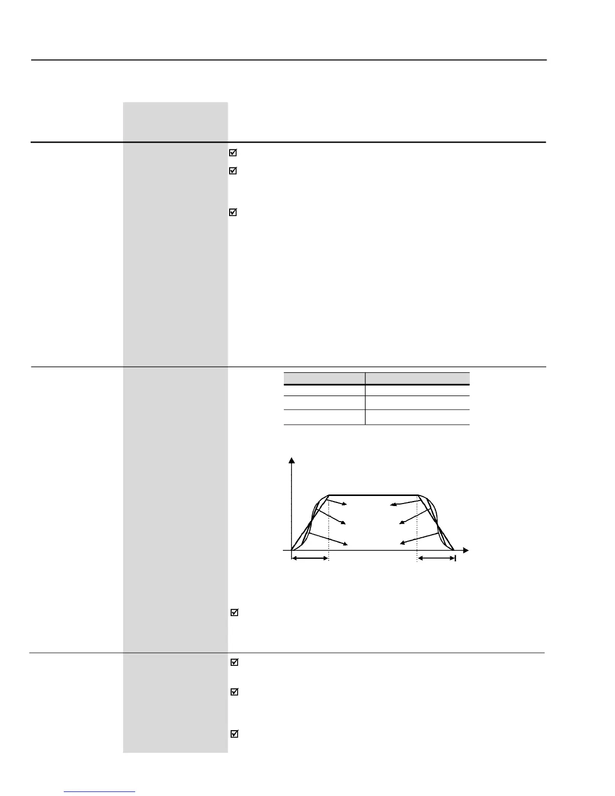
- Choosing S or linear ramp
The ramp S reduces the mechanical stress duringthe acceleration and
deceleration of the load.
Defines if the Frequency Reference Backup function is disabled (0) or
If P120 = Off, the inverter does not save the current reference value,
when the inverter is enabled again, it will restart from the minimum
This back-up function is applicable to the keypad (HMI), E.P., Serial,
Fieldbus and PID Setpoint (P525) references.
6.2 REGULATION PARAMETERS - P100 to P199
0.1s (< 99.9) -1s (> 99.9)
0.1s (< 99.9) -1s (> 99.9)
to 0.0 s results in noAcceleration ramp.
Defines the time to accelerate (P100) linearly from zero up to the
maximum speed (P134) or to decelerate (P101) linearly from the
maximum speed down to 0 rpm.
cceleration / deceleration time ramp 2 (P102 or
P103) can be made by reprogramming one of the digital inputs DI3 to
DI8. Refer to P265 to P270 in ramp 2.