EasyManua.ls Logo

WEG CFW-09 - Page 124

WEG CFW-09
362 pages
Print Icon
To Next Page IconTo Next Page
To Previous Page IconTo Previous Page
Loading...
125
CHAPTER 6 - DETAILED PARAMETER DESCRIPTION
Range
[Factory Setting]
Parameter
Unit
Description / Notes
P121
P133 to P134
Keypad Speed
[ 90 ]
Reference
1 rpm
To activate the and active: P221 = 0 or P222 = 0.
With P120 = 1 (On) the content of P121 is maintained (backup) even
when the inverter is disabled or turned off.
P122
(2)(11)
0 to P134
JOG or JOG+
[ 150 (125) ]
SpeedReference
1 rpm
P123
(2)(11)
0 to P134
JOG - Speed
[ 150 (125) ]
Reference
1 rpm
The JOG command source is defined at P225 (Local Mode) or P228
(RemoteMode).
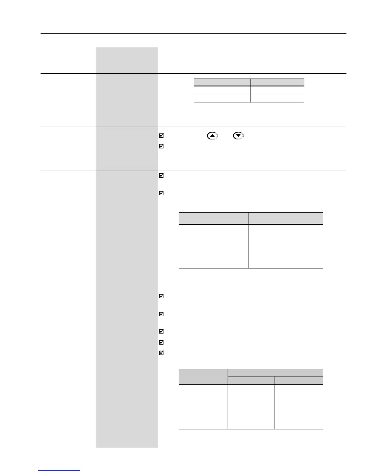
If the JOG command is selected for DI3 to DI8, one of the DigitalInputs
must be programmed as follows:
Digital Input
Parameters
DI3
P265 = 3 (JOG)
DI4
P266 = 3 (JOG)
DI5
P267 = 3 (JOG)
DI6
P268 = 3 (JOG)
DI7
P269 = 3 (JOG)
DI8
P270 = 3 (JOG)
Digital Inputs
Parameters
JOG+
JOG-
DI3
P265 = 10
P265 = 11
DI4
P266 = 10
P266 = 11
DI5
P267 = 10
P267 = 11
DI6
P268 = 10
P268 = 11
DI7
P269 = 10
P269 = 11
DI8
P270 = 10
P270 = 11
Table 6.3
- JOG Command selected by digital input
Table 6.4
- JOG+ and JOG- command selection
During the JOG command, the motor accelerates to the value defined
at P122, following the acceleration ramp setting.
ThedirectionofrotationisdefinedbytheForward/Reverse function(P223
or P226).
JOG is effective only with the motor at standstill.
The JOG+ and JOG- commands are always via Digital Inputs.
OneDIx mustbeprogrammedforJOG+ andanotherfor JOG-asfollows:
P120
Backup
0
Off
1
On
Table 6.2
- Speed reference backup

Table of Contents