CHAPTER 8 - CFW-09 OPTIONS AND ACCESSORIES
For applications that require high-speed accuracy, the actual motor speed
must be fed back via motor-mounted incremental encoder. The encoder is
connectedelectricallyto the inverter through the XC9 (DB9) connector of the
Function Expansion Board - EBA or EBB and XC9 or XC10 to EBC.
When the board EBA or EBB is used, the selected encoder should have the
following characteristics:
Power supply voltage: 12 Vdc, less than 200 mA current draw;
2 quadrature channels (90º) + zero pulse with complementary outputs
(differential): signals A, A, B, B, Z and Z;
“Linedriver” or “Push-Pull” output circuit type (level 12 V);
Electronic circuit isolated from encoder frame;
Recommended number of pulses per revolution: 1024 ppr.
For mounting the encoder on the motor, follow the recommendations bellow:
Couple the encoder directly to the motor shaft (use a flexible coupling
without torsional flexibility);
Both the shaft and the metallic frame of the encoder must be electrically
isolated from the motor (min. Spacing: 3 mm (0.119 in));
Use high quality flexible couplings to prevent mechanical oscillation or
The electrical connections must be made with shielded cable, maintaining a
minimum distance of about 25 cm (10 in) from other wires (power, control
cables, etc.). If possible, install the encoder cable in a metallic conduit.
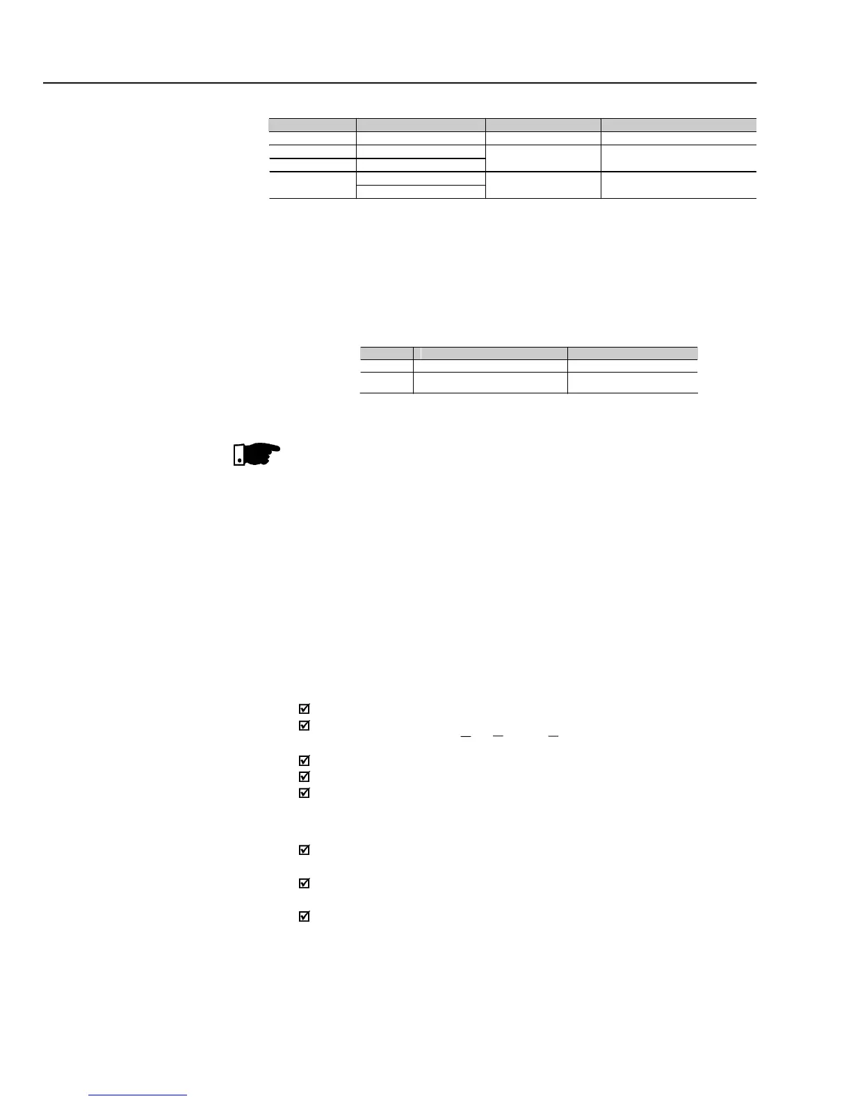
Trimpots configurations EBB board
Each group of switches must be set for the same option (ON or OFF for both).
When the outputs are set to (0 to 20) mA, it may be necessary to readjust the full scale.
For Size 1 models the CFI1 board (interface between the CC9 control board and the HMI) must
be removed to clear access to these switches.
EBB board selector switches configurations
Please download from www.weg.net the EBE Board Quick Guide.
Theexternalsignalandcontrolwiringmust beconnectedto XC(EBB),following
the same recommendations as for the wiring of thecontrol board CC9 (referto