EasyManua.ls Logo

WEG CFW-09 - Page 252

WEG CFW-09
362 pages
Print Icon
To Next Page IconTo Next Page
To Previous Page IconTo Previous Page
Loading...
253
CHAPTER 8 - CFW-09 OPTIONS AND ACCESSORIES
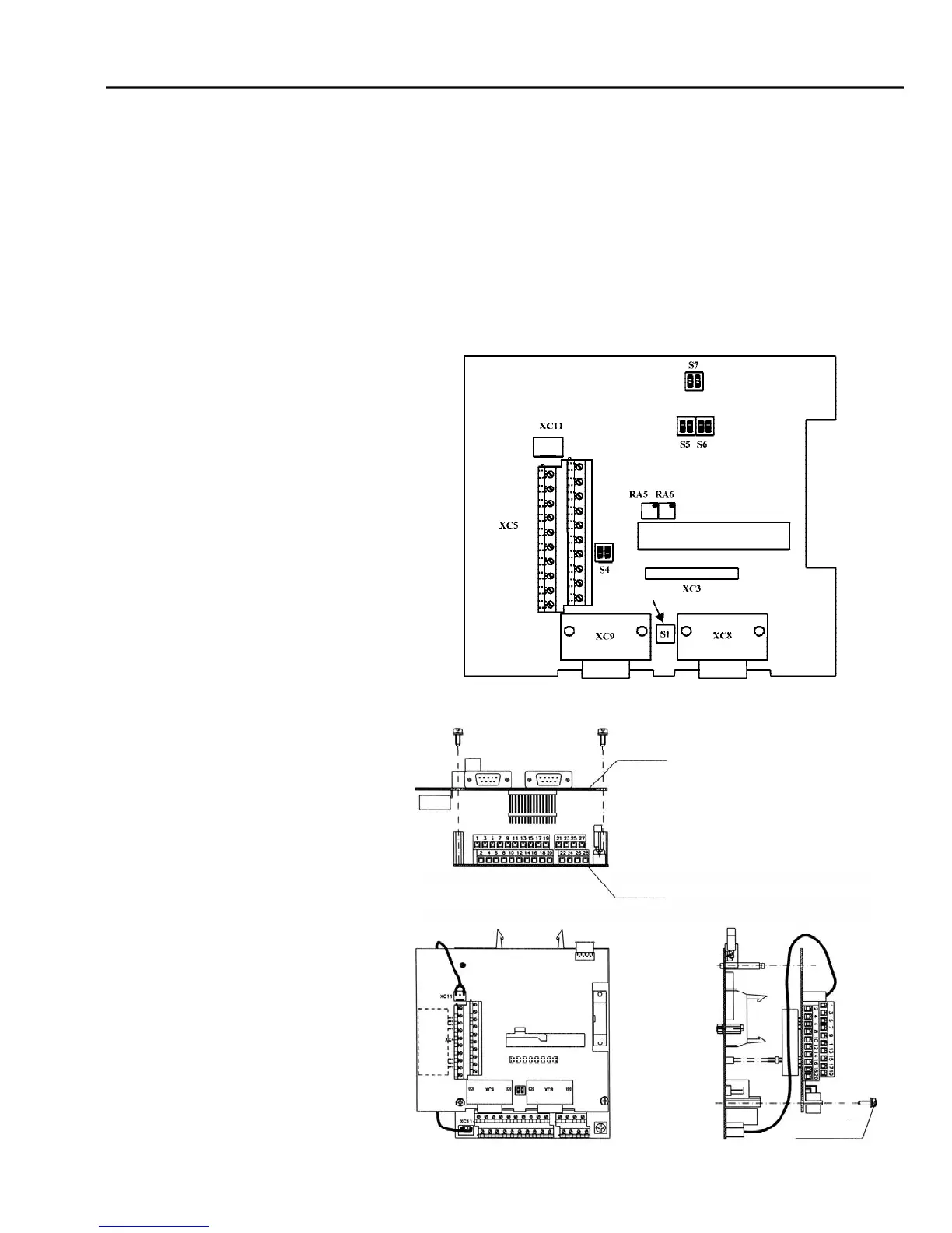
Mounting Instructions:
1.
Set the board configuration via S4, S5, S6 and S7 dip switches (refer to
table 8.4 a) );
2.
Carefully insert terminal block XC3 (EBB) into the female connector
XC3 of the CC9 control board. Check that all pins fit in the XC3 connector;
3.
Press on the EBB board (near XC3) and on the left top edge until com-
plete insertion of the connector and plastic spacer;
4.
Secure the board to the metallic spacers with the screws provided;
5.
Plug XC11 connector of the EBB board to the XC11 connector of the
(CC9) control board.
Figure 8.6
- EBB board installation procedure
M3 x 8 Screw
1Nm Torque
CC9 BOARD
EBB BOARD
Figure 8.5
- EBB board layout
EBB BOARD
CUTOUT
CUTOUT

Table of Contents