DIAGNOSTICS AND TROUBLESHOOTING
This chapter assists the user to identify and correct possible faults that
can occur during the CFW-09 operation. Guidance on Preventive
Maintenance is also provided.
When a fault is detected, the inverter is disabled and the Fault Code is
displayed on the readout in the E
form, where XX is the actual Fault
To restart the inverter after a fault hasoccurred, the inverter must be reset.
The reset can be made as follows:
Disconnectingand reapplyingAC power (power-on reset).
By pressing the key (manual reset).
Automatic reset through P206 (auto-reset).
By digital input: DIx = 12 (P265 to P270).
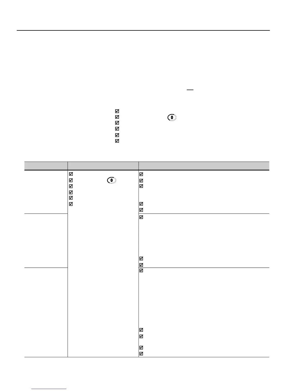
The table below defines each Fault Code, explains how to reset the fault
and shows the possible causes for each Fault Code.
Short-circuit between two motor phases
Short-circuit between braking resistor cables
When the output current reaches 2 x P295, caused by: very high
load inertia, acceleration ramp too fast or incorrect regulation and/
or configuration parameters
Transistor module shorted
P169 to P172 set too high
Power Supply voltage too high, check Ud in P004:
220-230 V Models - Ud > 400 V
380-480 V Models - Ud > 800 V
500-600 V and 500-690 V Models with power supply between
500-690 V models with power supply between 660 V and 690 V
Load inertia too high or deceleration ramp too short
P151 or P153 set too high
Power Supply voltage too low, DC Link check Ud in P004:
220-230 V power supply - Ud < 223 V
380 V power supply - Ud < 385 V
400-415 V power supply - Ud < 405 V
440-460 V power supply - Ud < 446 V
480 V power supply - Ud < 487 V
500-525 V power supply - Ud < 532 V
550-575 V power supply - Ud < 582 V
600 V power supply - Ud < 608 V
660-690 V power supply - Ud < 699 V
Auxiliary circuit fuse blown (only valid for 105 A and 130 A/220-230 V,
86 A to 600 A/380-480 V and 44A to 79 A/500-600 V refer to item 3.2.3)
Pre-charge contactor defective
P296 set to a voltage higher than the power supply voltage
- Faults and possible causes