CHAPTER 8 - CFW-09 OPTIONS AND ACCESSORIES
- Installation of the electronic board of the Fieldbus
The communication board that forms the Fieldbus Kit is installed directlyonto
the CC controlboard,connectedto theXC140connector andfixed byspacers.
Follow the Safety Notices in chapter 1.
If a Function Expansion Board (EBA/EBB) is already installed, it must
be removed provisionally. For the frame size 1 you must remove the
lateral plastic cover of the product.
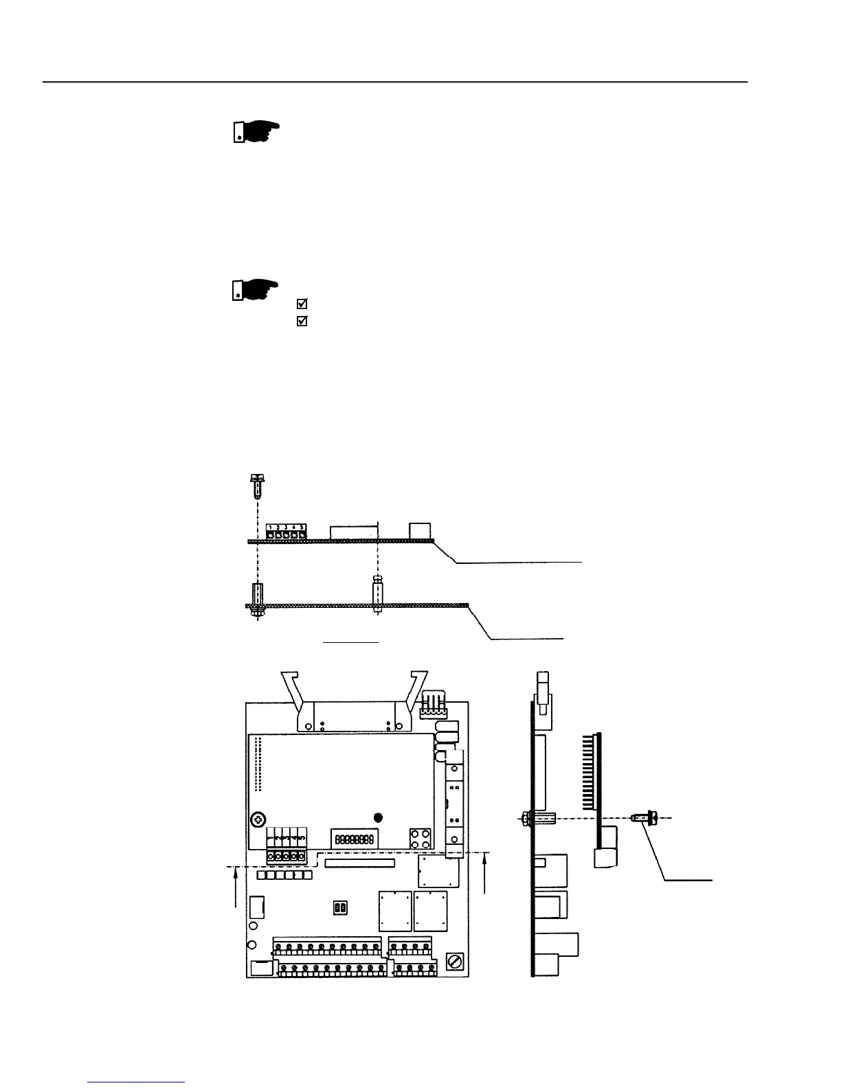
Remove the bolt from the metallic spacer near to the XC140 (CC9)
Connect carefullythe pin connector of the Fieldbus board to the female
connector XC140 of the CC9 control board. Check the exact
coincidence of all pins of the XC140 connector (refer to figure 8.35).
The chosen Fieldbus option can be specified in the suitable field of the
In this case the CFW-09 will be suppliedwith all needed components already
installed in the product. For later installation you must order and install the
desired Fieldbus kit (KFB).