CHAPTER 8 - CFW-09 OPTIONS AND ACCESSORIES
The kit for through surface mounting is composed of metallic supports that
must be mounted on the rear of the CFW-09 frames 3 to 8 to allow through
surface mounting. For further information refer to item 3.1.3.3, figure 3.4 and
table 3.4. Degree of protection is NEMA 1/IP20.
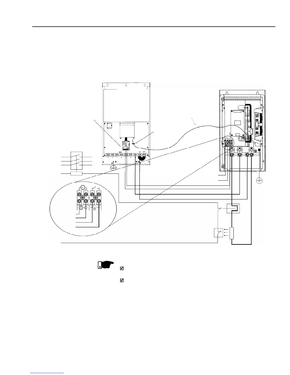
Figure 8.34 shows the connection of the braking module to the inverter, as
well as the connections of the resistor to the braking module. It shows also
the inclusion of a thermal relay and a thermostat in contact with the resistor
body, thus ensuring its thermal protection. The connection cables between
the inverter and the module and between the module and the braking resistor
must be dimensioned according to the thermal braking cycle.
- Connections between the DBW, the CFW-09 and the braking resistor
CFW-09 can be connected to Fieldbus networks allowing its control and
parameter setting. For this purpose you need to include an optionalelectronic
board according to the desired Fieldbus standard: Profibus DP, DeviceNet or
Through the powercontacts ofthe bimetallicoverloadrelaycirculates Direct
Current during the DC-Braking process.
The DBW-02 has a duplicated XC3 connector (A and B). The XC3B is for
connecting other DBW-02 module for parallel operation. It is possible to
connect up to 3 DBW-02 modules in parallel. The interconnecting cable
should be limited to 2 meters maximum cable length.