CHAPTER 6 - DETAILED PARAMETER DESCRIPTION
P213 = 0: Zero speed disable without timing.
P213 > 0: Zero speed disable will only become active after the time
delay set in P213. Timing starts when the zero speed zone conditions
are met. If these conditions are no longer met during the delaytime, the
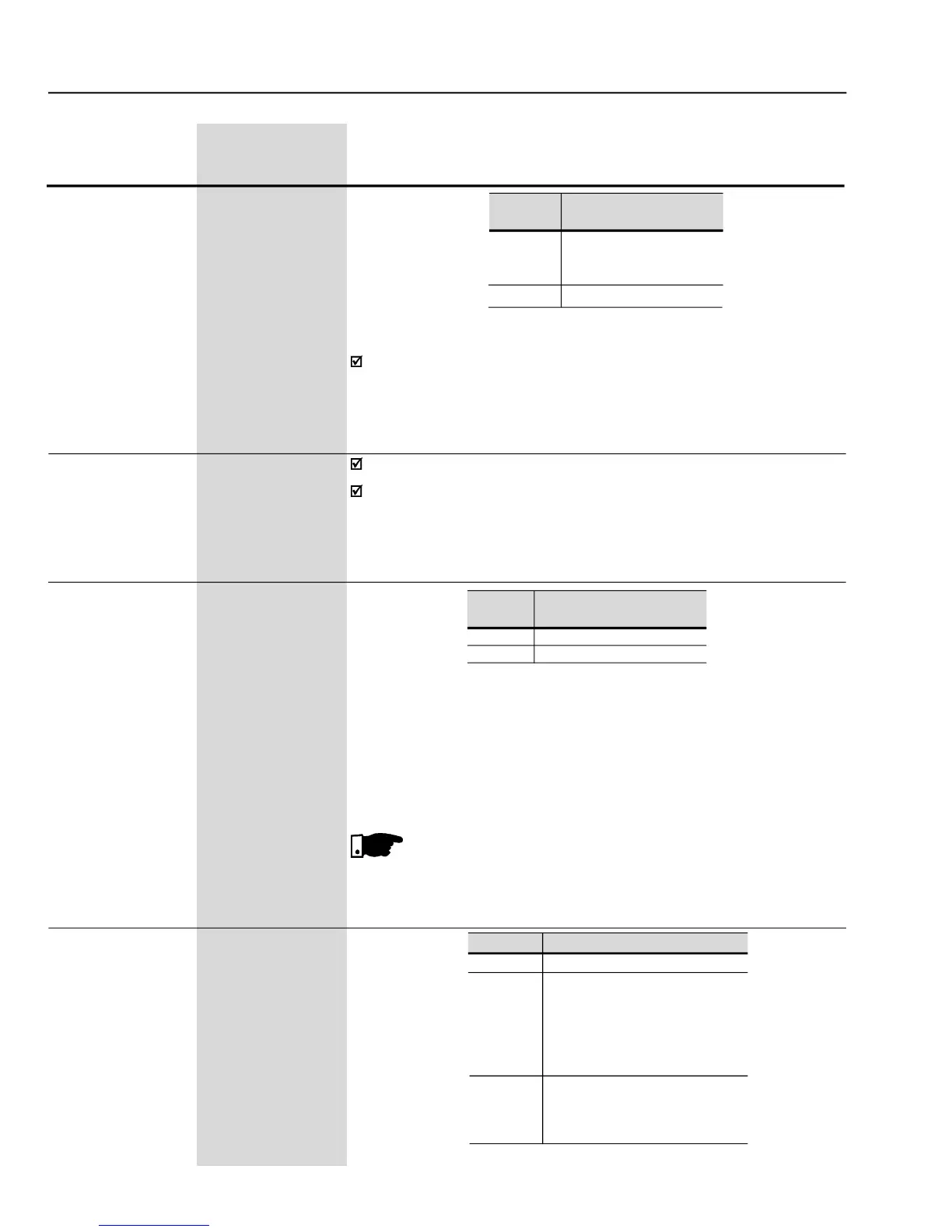
P001 (Speed ref. N*) > P291
When the PID Regulator is active (P203 = 1) and inAutomatic mode, the
inverter leaves the Zero Speed, besides the programmed condition in
P212, onlywhen the PID input error(thedifference between setpointand
process variable) is higher thanthe value programmed in P535.
Condition to leave zero speed disable
Actuation line phase loss detection
The phase loss detector is active when:
P214 = On and the CFW-09 is enabled.
The display indication and the updating of the fault memory happen 3
seconds after the fault has occurred.
The phase loss detection is not available in types up to 28 A for
220-230 V and380-480 V supply voltage and in types up to 14Afor
500-600 V supply voltage, independentlyof the value set in P214.
Transfers the current parameter
values and the content of the
User 1/2 Memories to the non volatile
EEPROM memory of the Keypad
(HMI). The current inverter
parameters are not changed.
Transfers the content of the Keypad
(HMI) memory to the current inverter
parameters and to the User 1/2