CHAPTER 8 - CFW-09 OPTIONS AND ACCESSORIES
It reads the content of an internal group of bits that must compulsorily in
a numerical sequence. This function has the following structure for the
read and response messages (the values are always hexadecimal, and
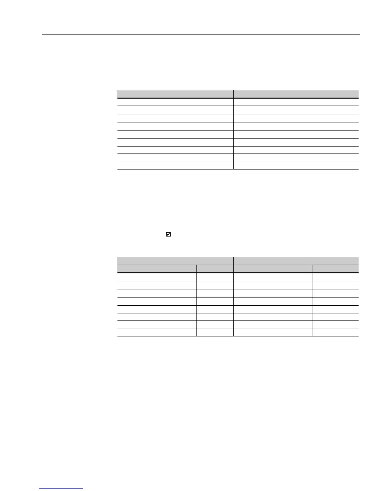
each filed represents one byte):
Initial bit address (byte high)
Initial bit address (byte low)
Number of bits (byte high)
Number of bits (byte low)
Byte Count Field (number of data bytes)
Each response bit is placed at a position of the data bytes sent by the
slave. The first byte, from the bits 0 to 7, receives the first 8 bits from the
initial address indicated by the master. The other bytes (if the number of
the read bits is higher than 8) remainin the same sequence.If the number
of the read bits is not a multiple of 8, the remaining bits of the last byte
should be filled out with 0 (zero).
Example: reading of the status bits for general enable (bit 1) and
direction of rotation (bit 2) of then CFW-09 at the address 1:
Initial bit address (byte high)
Initial bit address (byte low)
Number of bits (byte high)
Number of bits (byte low)
Status of the bits 1 and 2
It reads the content of a group of registers that must be compulsorilyin a
numerical sequence. This function has following structure for the read
andresponse messages (the values are always hexadecimal values, and
each field represents one byte):
As the number of read bits in the example is smaller than 8, the slave
required only1 bytefor the response. The value of the byte was 02h, t
as binaryvalue will havethe form 00000010.As thenumberof read bits is
equalto 2, onlythetwo less significant bits, that have thevalue0 =general
disable and 1 = direction of rotation, are of interest. The other bits, as
they did not be requested, are filled out with 0 (zero).