CHAPTER 3 - INSTALLATIONANDCONNECTION
Thecontrol wiring (analoginputs/outputs,digitalinputs/outputs andrelayoutputs)
is made on the following terminal blocks of the Electronic Control Board CC9
(refer to location in figures 3.7, item 3.2.2).
Digital and Analog Signals
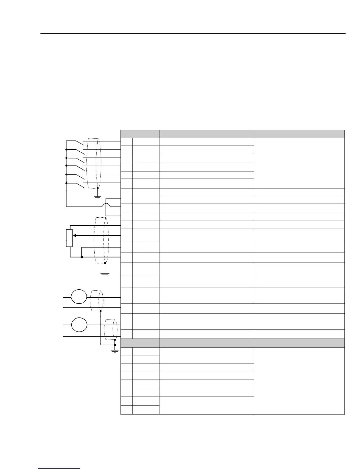
- XC1/XC1A control terminals description (CC9 board) - Active high digital inputs
= normally closed contact,
FWD / REV Section (Remote Mode)
Digital inputs 24 Vdc source
0 V Reference of the 24 Vdc Source
Positive Reference for Potentiometer
Speed Reference (Remote Mode)
Negative Reference for Potentiometer
0 V Reference for Analog Outputs
Analog Output: Motor Current
0 V Reference for Analog Outputs
Relay Output - Speed > P288 (N > Nx)
Relay Output - Speed > P288 (N > Nx)
Relay Output - Speed Reference >
6 Isolated Digital Inputs
Minimum High Level: 18 Vdc
Grounded by a 249 resistor
+ 5.4 Vdc 5 %, Capacity: 2 mA
Valid for AI1 and AI2 differential,
resolution: 10 bits, (0 to 10) Vdc or
(0 to 20) mA / (4 to 20) mA
[(0 to 20) mA / (4 to 20) mA]
Grounded by a 5.1 resistor
The following diagram shows the control wiring with the digital inputs as active
highas set on factory (jumper between XC1:8 and XC1:10).