CHAPTER 8 - CFW-09 OPTIONS AND ACCESSORIES
The initial and the en points of the network must be terminated with the
characteristicimpedance in order to prevent reflections. The DB 9 cablemale
connector has the suitable termination. When the inverter is the first or the
last of the network, theterminationswitch must be set to Pos. “ON”. Otherwise
set the switch to Pos. “OFF”. The terminating switch of the PROFIBUS DP
board must be set to 1 (OFF).
Transfer Rate (baud rate)
The transfer rate of a Profibus DP network is defined during the master
configuration and onlyonerateis permittedinthe same network. TheProfibus
DP board has automatic baud rate detection and the user does not need to
configure it on the board. The supported baud rates are: 9.6 kbits/s, 19.2kbits/
45.45 kbits/s, 93.75 kbits/s, 187.5 kbits/s, 500 kbits/s, 1.5 Mbits/s, 3 Mbits/
6 Mbits/s and 12 Mbits/s.
The node address is established by means of two rotating switches on the
electronicProfibusDPboard,permittingtheaddressingfrom 1 to99addresses.
Looking onto the front view of the board with the inverter in normal position,
the switch at left sets the ten of the address, while the left switch sets the unit
Address = (set left rotary switch x 10) + (set right rotary switch x 1)
The node address can not be changed duringoperation.
Configuration File (GSD File)
Each element of a Profibus DP network is associated to a GSD file that has
all information about the element. This file is used by program of the network
configuration. Use the file with the extension .gsd stored on the floppy disk
contained in the Fieldbus kit.
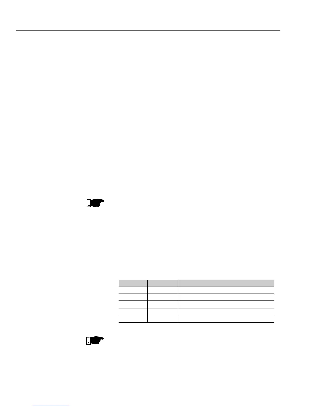
- Signaling LED of the Fieldbus board status
Fault during the test of the ASIC and Flash ROM
Board has not been initialized
Board has been initialized and is operating
Fault during the RAM test
Fault during the DPRAM test
Theredfaultindications mean hardware problems of theelectronic board.The
reset is realized by switching OFF / ON the inverter. If the problem persists,
replace the electronic board.
The electronic board is also fitted with four other bicolor LEDs placed at the
right bottom side, indicating the Fieldbus status according to the figure below:
The electronic board has a bicolor LED at rightunderside indicating the status
of the Fieldbus according to the table 8.16 and figure 8.40 below: