CHAPTER 6 - DETAILED PARAMETER DESCRIPTION
1, and the DI1 status is the most significant bit (MSB).
DI1 = Active (+24 V); DI2 = Inactive (0 V);
DI3 = Inactive (0 V); DI4 = Active (+24 V);
DI5 = Inactive (0 V); DI6 = Inactive (0 V);
DI7 = Inactive (0 V); DI8 = Inactive (0 V);
This is equivalent to the binary sequence:
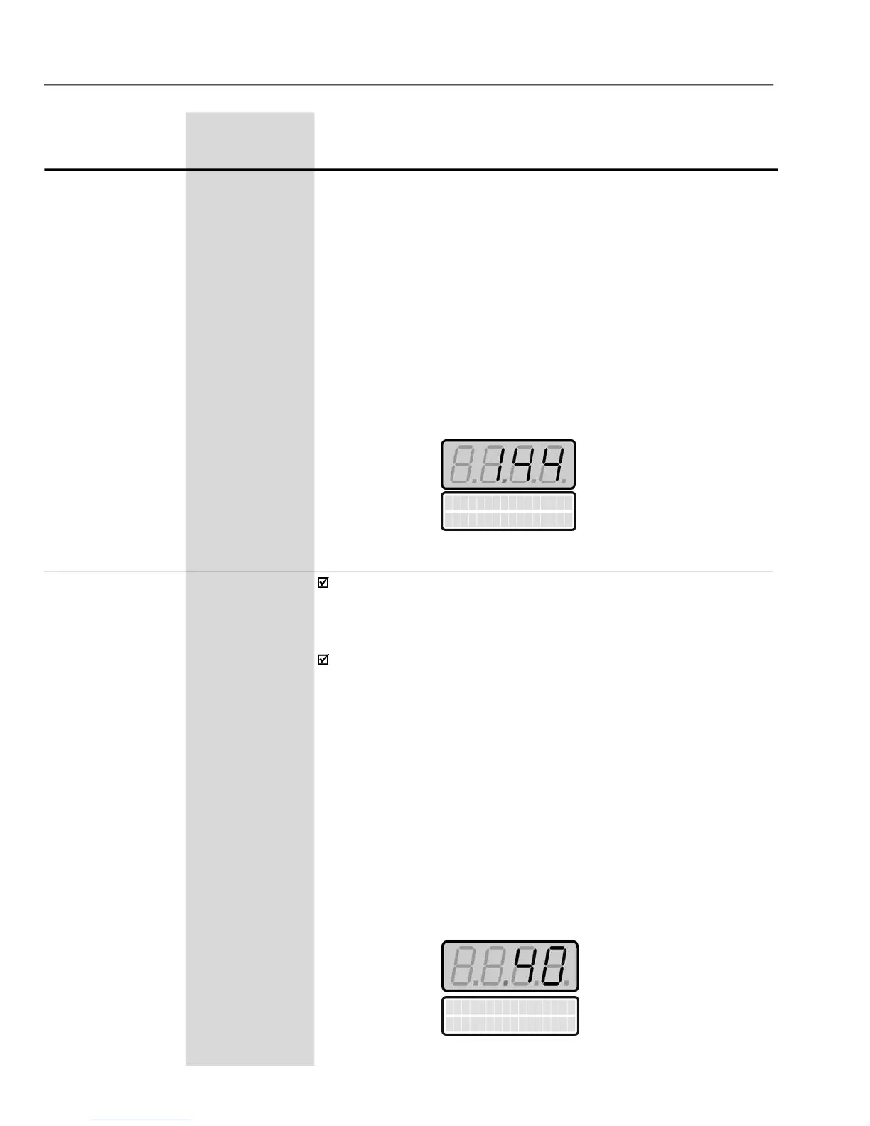
Which corresponds to the decimal number 144.
The Keypad displays will be as follows:
Indicates on the Keypad LCD Display the status of the 2 Digital Outputs
of the I/O Expansion Board (DO1, DO2) and the 3 Relay Outputs of the
controlboard. Number1 stands forActive andnumber 0stands forInactive,
in the following order: DO1, DO2, RL1, RL2, RL3.
The LED display shows a decimal value related to the status of the 5
Digital and RelayOutputs, where the status of each output is considered
one bit of a binary number where:
Inactive = 0, Active = 1, and the status of DO1 is the most significant bit
(MSB). The 3 least significant bits are always ‘0’.
DO1 = Inactive; DO2 = Inactive
RL1 =Active: RL2 = Inactive; RL3 = Active
This is equivalent to the binary sequence:
Which corresponds to the decimal number 40.
The Keypad displays will be:


 To Next Page