CHAPTER 6 - DETAILED PARAMETER DESCRIPTION
The speed at which the transition from Sensorless Vector Control to I/F
(Scalar Control with Imposed Current) occurs. The minimum speed
recommended for Sensorless Vector Control is 18 rpm for 60 Hz motors
and 15 rpm for 50 Hz motors, with 4 poles.
3 the CFW-09 will always operatein Sensorless VectorMode
when P202 = 3, (there is no transition to the I/F Mode).
The current level to be applied on the motor in the I/F Mode is set at
Scalar Control with imposed current means onlycurrentcontrol working
with current reference level adjusted byP136. There is no speed control,
just open loop frequency control.
..........................
............................
.........................
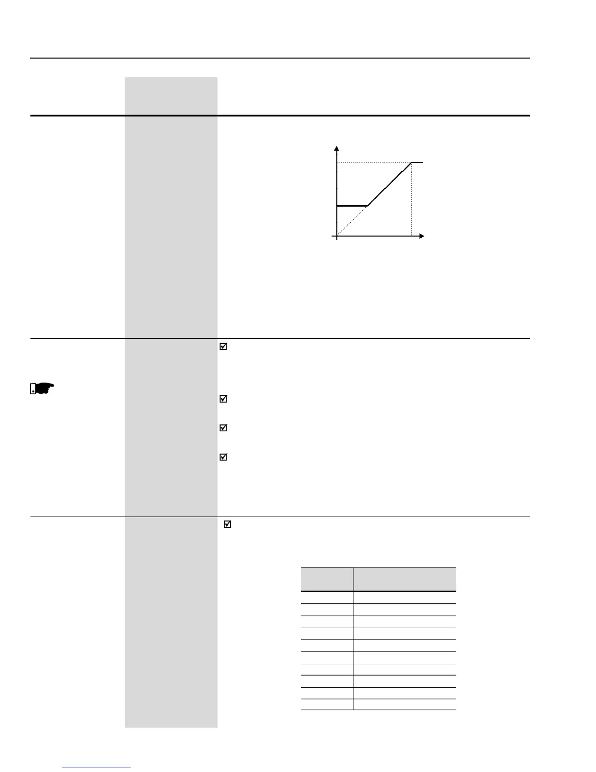
- Speed limits considering the “Dead Zone” active (P233 = 1)
Sets the current to be applied to the motor when in I/F Mode. I/F Mode
occurs when the motor speed is lower than the value defined by
Current reference for I/F mode


 To Next Page