CHAPTER 6 - DETAILED PARAMETER DESCRIPTION
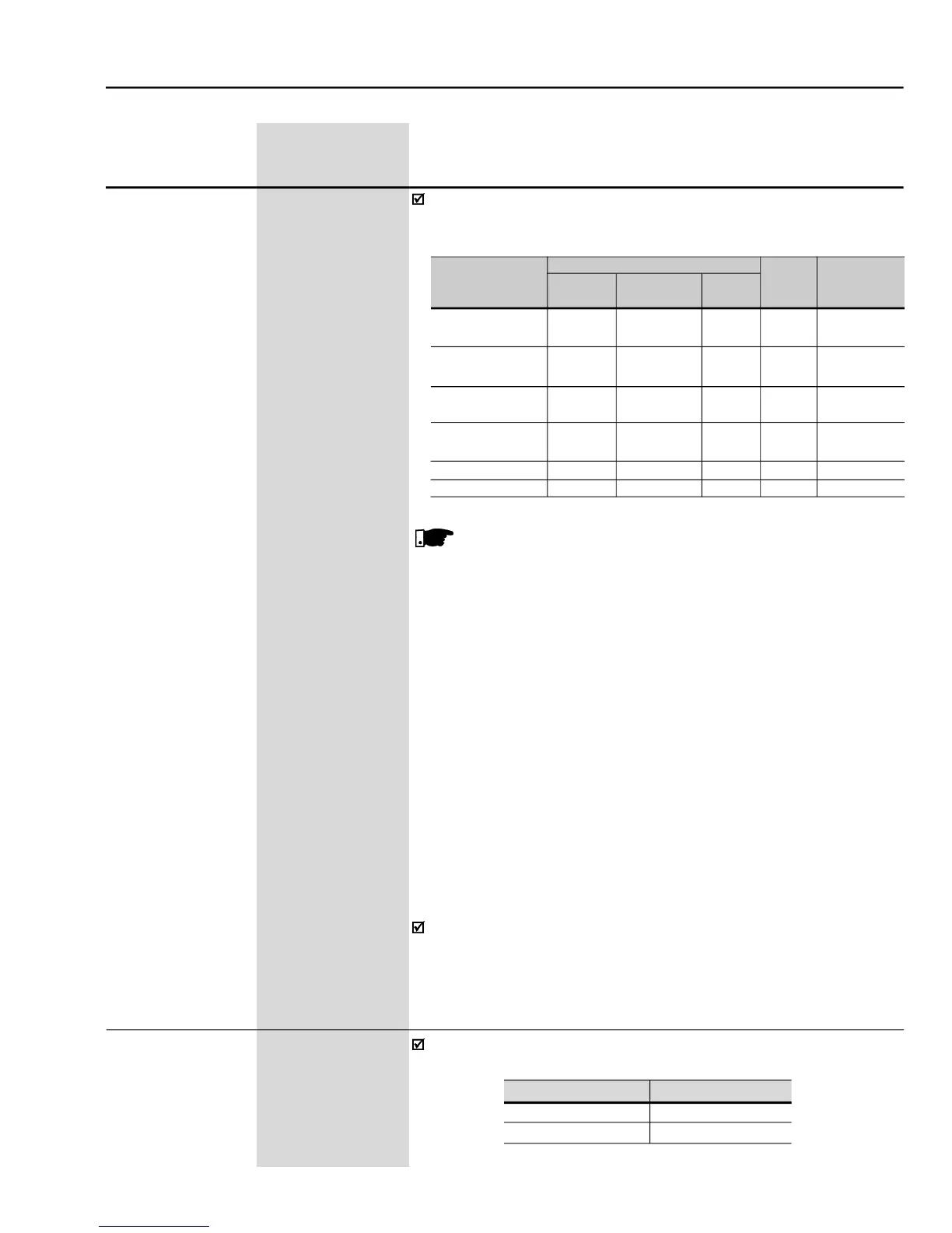
Some examples of initial settings of the PID Regulator Gains and PID
Ramp Times for some applications mentioned in item 6.5.1, are shown
- Suggestions for gain settings of the PID regulator
For temperature and level control, the action type will depend
on the process. For instance, in the level control, when the
inverter drivesthemotorthatremovesfluidfrom a tank,the action
will be contrary as when the inverter drives the motor that fills a
tank and thus the fluid level increases and the inverter should
increase the motor speed to lower the fluid level, otherwise the
inverter action that drives the pump motor to pump fluid into the
Incaseof levelcontrol, thesetting of theintegralgain willdepend
onthe time required tofill thetank from the minimum acceptable
level up the desired level, in the following conditions:
For the direct action, the time should be measured by
considering the maximum input flow and the minimum output
In the inverse action, the time should be measured by
considering the minimum input flow and the maximum output
The equation to calculatean initial value for P521 (PID Integral Gain) as
a function of the system response time, is presented below:
It selects the feedback input (Process Variable) of the PID regulator:
 Loading...


