CHAPTER 8 - CFW-09 OPTIONS AND ACCESSORIES
To avoid reflection, the initial and the end points of the network must be
terminatedwith the characteristicimpedance. Thus a 120-ohms/0.5W resistor
must be connected between the pins 2 and 4 of the Fieldbus connector.
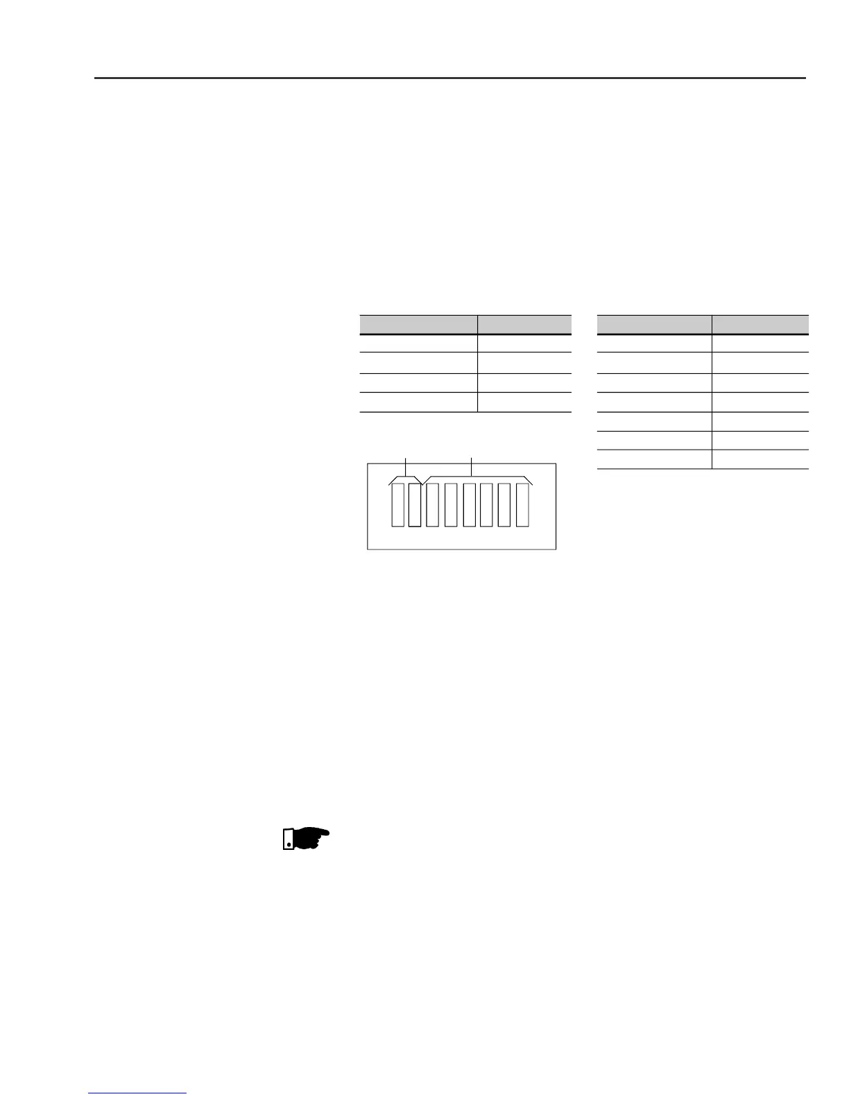
There are three different baud rates for the DeviceNet: 125 kbits/s, 250 kbits/
s or 500 kbits/s. Choose one of these baud rates by setting the DIP switches
The node address is selected through the six DIP switches on the electronic
board, permitting an addressing from 0 to 63 addresses.
- Baud rate configuration an addressing to the DeviceNet
Configuration File (EDS File)
Each element of a DeviceNet network is associated to an EDS file that has all
information about the element. This file is used by program of the network
configurationduring itsconfiguration. Usethefile withtheextension .edsstored
on the floppy disk contained in the Fieldbus kit.
Setting parameter P309 to 4, 5 or 6 selects 2, 4 or 6 input/output words (refer
With the assistance of the network configuration software define the number
of words for the device according to thevalue set onparameterP309. Thetype
of connection used for data exchange shall be set for “Polled I/O”.
The PLC (master) must be programmed for Polled I/O connection.
The electronic board has a bicolor LED at right topside indicating the status of
the Fieldbus according to the table 8.16.