CHAPTER 8 - CFW-09 OPTIONS AND ACCESSORIES
As shown in the figure 8.58, CFW-09RB unit is fitted with a capacitor bank
Externally is mounted a network reactance and a capacitive filter.
By switching the IGBTs bridge, the energy can be transferred in a controlled
way from the network to the capacitor bank. One can say that by means of
the switching process, the CFW-09RB emulates a resistive load. There is
alsoa capacitive filter topreventthebridgeswitchinginterferesin other network
loads. To complete this drive, the use of a CFW-09HD is required that drives
the motor and its load. This drive is shown in figure 8.58 by the second de
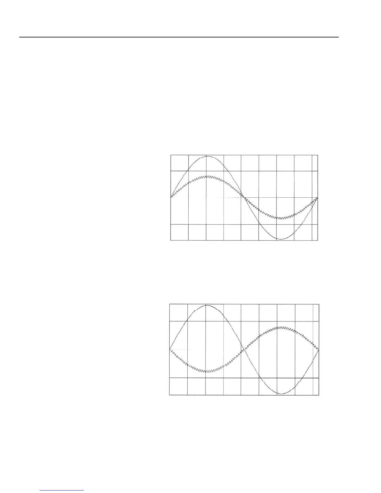
IGBTs bridge. Figure 8.59 a) shows wave shapes of the CFW-09 RB input
voltage and current, when the motor at the drive output is operating normally.
Figure 8.59 b) shows the wave shapes of the CFW-09 RB input voltage and
current, when the motor at the drive output is submittedto a braking process.
For more details, refer to the CFW-09 RB Regenerative Converter Manual.
Functioning during operation as motor
Functioning during the braking process
 Loading...


