EasyManua.ls Logo

WEG CFW-09 - General Information; About this Manual; Software Version; About the CFW-09

WEG CFW-09
362 pages
Print Icon
To Next Page IconTo Next Page
To Previous Page IconTo Previous Page
Loading...
38
CHAPTER 2 - GENERALINFORMATION
Sensors:
-Groundfault
- Phase-fault
=Phase-fault only
fromsize 3and up.
Analog
Inputs
(AI1...AI2)
PC
PLC
DCS
Digital
Inputs
(DI1 ... DI6)
Internalelectronics powersuppliesand
control/powerinterfaces
RS-232
(optional)
PC
POWER
CONTROL
Three-phase
rectifier
Motor
IGBT
Inverter
Power
Supply
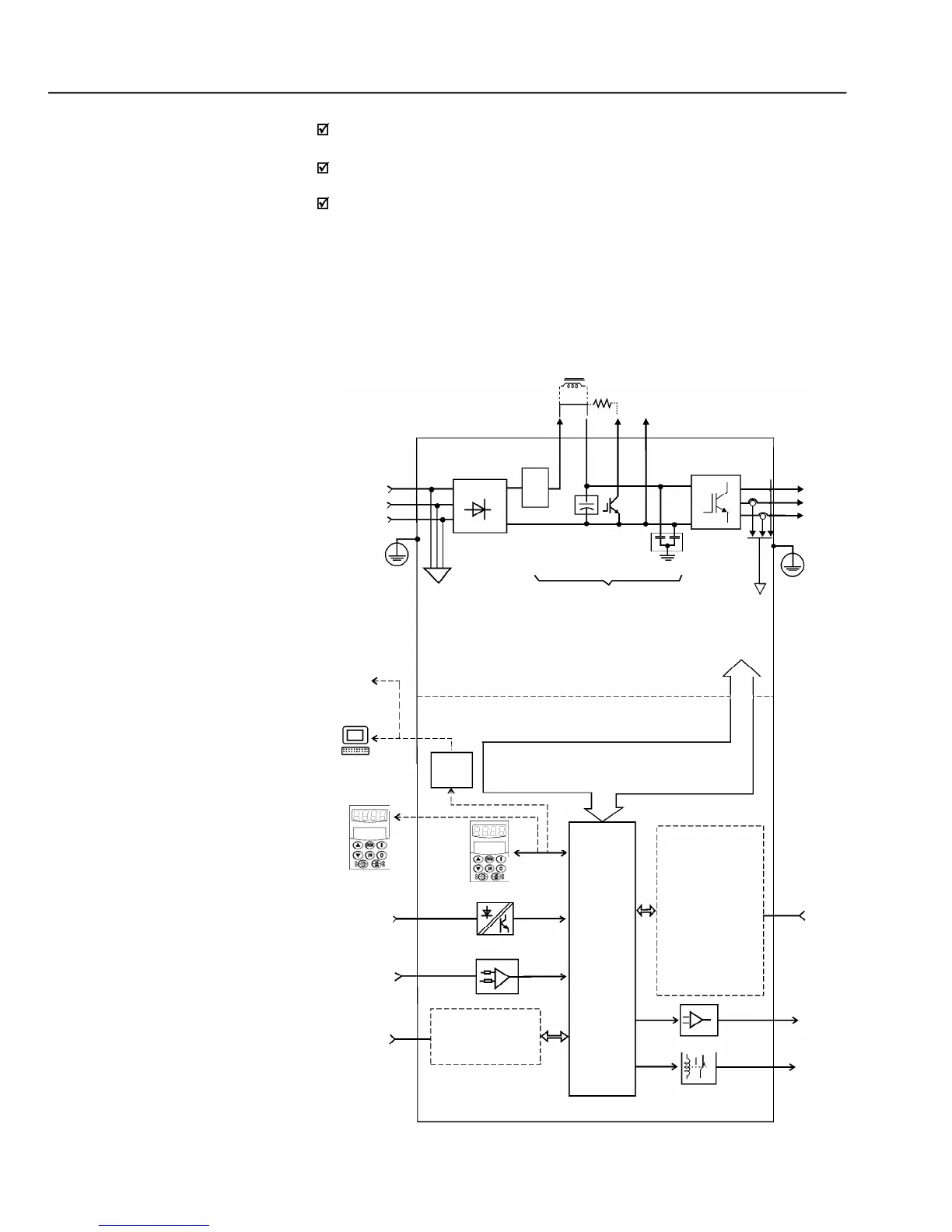
= DCLinkchokeconnection (optional)
onlyfromsize 2 and up.
= DB resistor connection.Up tosize 7
only. Option forsizes 4 to 7.
= DCLink connection.
Pre-
charge
SuperDrive Software
Capacitor
Bank
RFI filter
Keypad
FIELDBUS (Optional):
- Profibus DP
- DeviceNet
- EtherNet/IP
"CC9"
Control
Boardw/
32bits
"RISC"
CPU
EBA/EBBEXPANSION:
(optional)
- isolated RS-485
- 1 digital input
A
1 x14bit anal.input
2x14bitanal.outputs
B
1 isola. 4 to 20mAIn.
2 isola. 4 to 20 mA out.
- 2 digitaloutputs
- 1 encoder In/Out.
- 1 PTC input
{
{
External
Control
Analog
Outputs
(AO1...AO2)
Relay
Outputs
(RL1... RL3)
Keypad
(remote)
DCLink
Feedbacks:
-voltage
-current
PE
PE
Modbus-RTU
Figure 2.1
- CFW-09 block diagram
Human- MachineInterface
The Sensorless Vector Control permits high torques and quick response,
even at very low speeds and during the starting of the motor;
The “Optimal Braking function allows controlledmotor brakingwithout using
a Dynamic Braking (DB) resistor;
“Self-tuningauto-tunefunctionwithVectorControl,permittingautomaticsetting
of the control regulators and control parameters by means of the automatic
identification of the motor and the load parameters.
Technical specifications for each model of CFW-09 are described in chapter 9.
The block diagram below gives a general viewof the CFW-09:

Table of Contents

Other manuals for WEG CFW-09

Related product manuals