EasyManua.ls Logo

WEG CFW-09 - Page 55

WEG CFW-09
362 pages
Print Icon
To Next Page IconTo Next Page
To Previous Page IconTo Previous Page
Loading...
56
CHAPTER 3 - INSTALLATIONANDCONNECTION
NOTE!
The wire sizing indicated in table 3.5 are reference values only. The exact
wire sizing depends on the installation conditions and the maximum
acceptable line voltage drop.
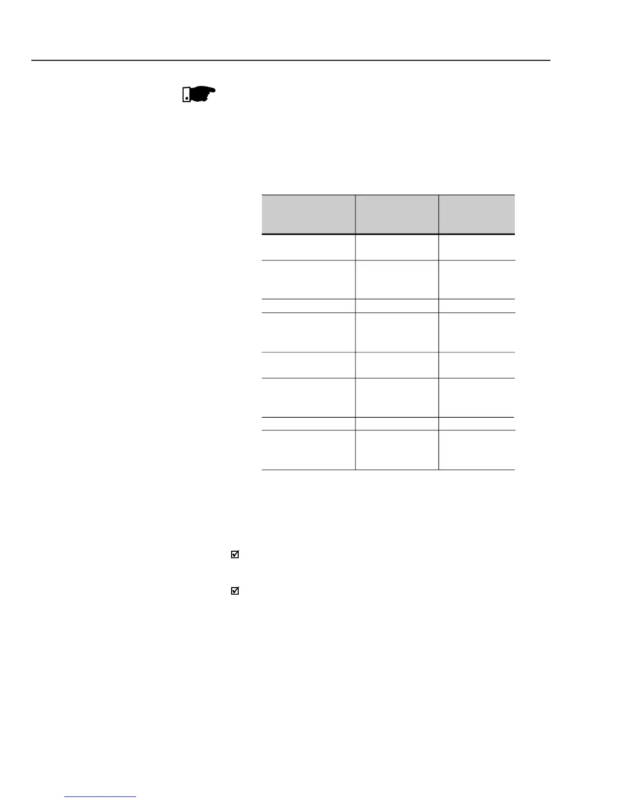
The tightening torque is as indicated in table 3.6. Use 75ÂșC copper wire
only.
Table 3.6
- Recommended tightening torque for power and
grounding connections
Grounding
Wiring
N.m (Ibf.in)
1.00 (8.85)
2.00 (17.70)
4.50 (39.83)
4.50 (39.83)
4.50 (39.83)
15.50 (132.75)
15.50 (132.75)
30.00 (265.50)
CFW-09Rating
A/Volts
6 A to 13 A/220-230 V
3.6 A to 13 A/380-480 V
16 A to 28 A/220-230 V
16 A to 24 A/380-480 V
2.9 A to 14 A/500-600 V
30 A/380-480 V
45 A/220-230 V
38 A to 45 A/380-480 V
22 A to 32 A/500-600 V
54 A to 86 A/220-230 V
60 A to 86 A/380-480 V
105 A to 130 A/220-230 V
105 A to 142 A/380-480 V
44 A to 79 A/500-600 V
180 A to 240 A/380-480 V
312 A to 600 A/380-480 V
107 A to 472 A/500-690 V
100 A to 428 A/660-690 V
Power Cables
N.m (Ibf.in)
1.76 (15.58)
2.00 (17.70)
1.40 (12.30)
1.40 (12.30)
3.00 (26.10)
15.50 (132.75)
30.00 (265.50)
60.00 (531.00)
Line Fuses
For protecting the input rectifier diodes and the wiring, use UR Type
(Ultra-Rapid) fuses with i
2
t equal or lower than indicated in table 3.5.
Standard fuses may be used optionally at the input with currents as
indicated in table 3.5, or circuit breakers dimensioned for 1.2 x rated
inverter input current for the CT or the VT operation (refer to items 9.1.2
to 9.1.5).
However in thiscase, onlythe installation will be protected against short-
circuit, but not the diodes of the rectifier bridge at the inverter input. This
option may damage the inverter in case of short-circuit of some internal
component.

Table of Contents

Other manuals for WEG CFW-09

Related product manuals