Maintenance
2303−1/A1
Winterthur Gas & Diesel Ltd.
5/ 6
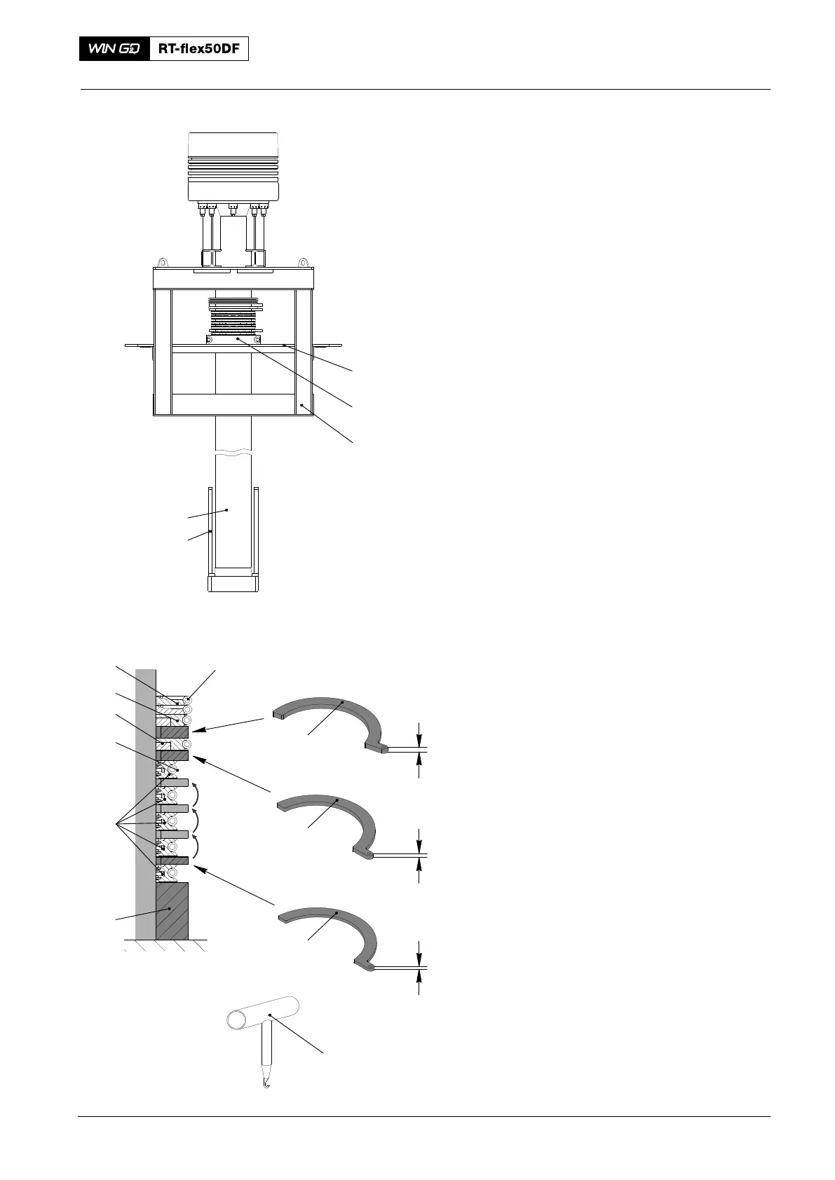
6. Assemble
1) Attach two parts of the clamp ring
(94345B, Fig. 7) to the piston rod (2).
2) Put the ring support (4) and the 3-part
scraper ring (5) on the clamp ring
(94345B).
3) Use the assembly tool (94345E) to
attach the tension spring (3) to the ring
support (4).
4) Put the two distance pieces
(94345F−9) on the ring support (4).
5) Put the next ring support (4) and the
3-part scraper ring (5) on the distance
piece 94315F−9).
6) Use the assembly tool (94345E) to
attach the tension spring (6) to the ring
support (4).
7) Put the two distance pieces
(944345F−11) in position on the ring
support (4).
8) Put the next ring support (4) and the
3-part scraper ring (5) on the distance
piece 94315F−11). Make sure that
there is an equal distance between the
three parts.
9) Use the assembly tool (94345E) to
attach the tension spring (6) to the ring
support (4).
10) Move the two distances pieces
(94345F−11) up.
11) Do step 8) and step 10) for the next two
ring supports and 3-part scraper rings.
12) Put the distance piece (94345F−13) in
position.
13) Put the two 4-part gaskets (7) and the
two 4-part gaskets (8) in position.
14) Put the 4-part scraper ring (9) on the
distance piece 94315F−13).
15) Use the assembly tool (94345E) to
attach the tension spring (3) to the
scraper ring (9).
16) Remove all distance pieces (94345F).
17) Remove the clamp ring (94345B).
2016
Removal, Disassemble, Measure Worn Parts, Assemble, Installation
016.571/08
94345
2
94345B
94350
1
7
8
004.284/98
94345E
Fig. 7
009.656/02
009.655/02
009.654/02
94345F−9
94345F−11
94345F−13
13 mm
11 mm
9 mm
94345B
3
4, 5
6
9