Maintenance
2722−2/A1
Winterthur Gas & Diesel Ltd.
7/ 7
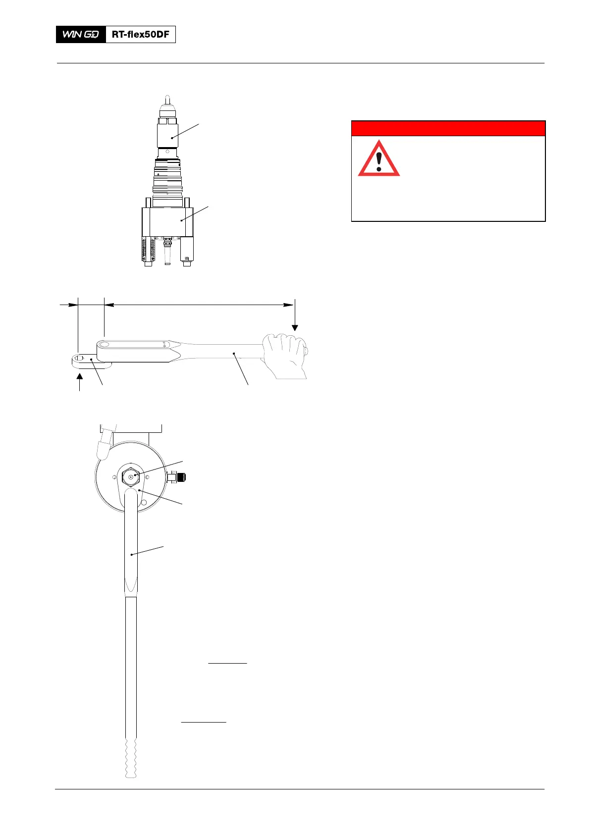
3.8 Injection Valve − Assemble
WARNING
Injury and Damage Hazard:
Do not use copper paste in
this procedure. Copper
paste can be a conductor
of electricity. Injury to
personnel and damage to
equipment can occur.
1) Make sure that the sealing faces of the
injection valve (2, Fig. 6):
D Are clean and dry
D Are in a satisfactory condition
D Have no lubricant.
2) Apply a thin layer of Never Seez
NSBT8 to the threads and seating face
of the locknut (1).
3) Attach the locknut (1) to the injection
valve (2) with your hand.
4) Refer to the formulas shown where:
D TS = the applicable torque setting
for the torque spanner.
D TT = the specified torque setting for
the coupling nut.
D D1 = the distance from the center of
the square drive to the center of the
hand grip.
D D2 = the distance from the center of
the square drive to the center of the
adapter.
5) Use the torque spanner (94012) and
the wrench extension (94269C−46) to
torque the locknut to 500 +30 Nm.
6) Do a check of the injection valve, refer
to paragraph 3.1 and paragraph 3.2.
2018−02
Injection Valve: Disassemble, Checks, Assemble
94012
94269C−46
D2 D1
Fig. 6
1
94012
94269C-46
= 459.7 Nm
1
2
TS for coupling nut:
500 x 800
70 + 800
TS = TT x D1
D2 + D1