Maintenance
2728−1/A1
Winterthur Gas & Diesel Ltd.
5/ 6
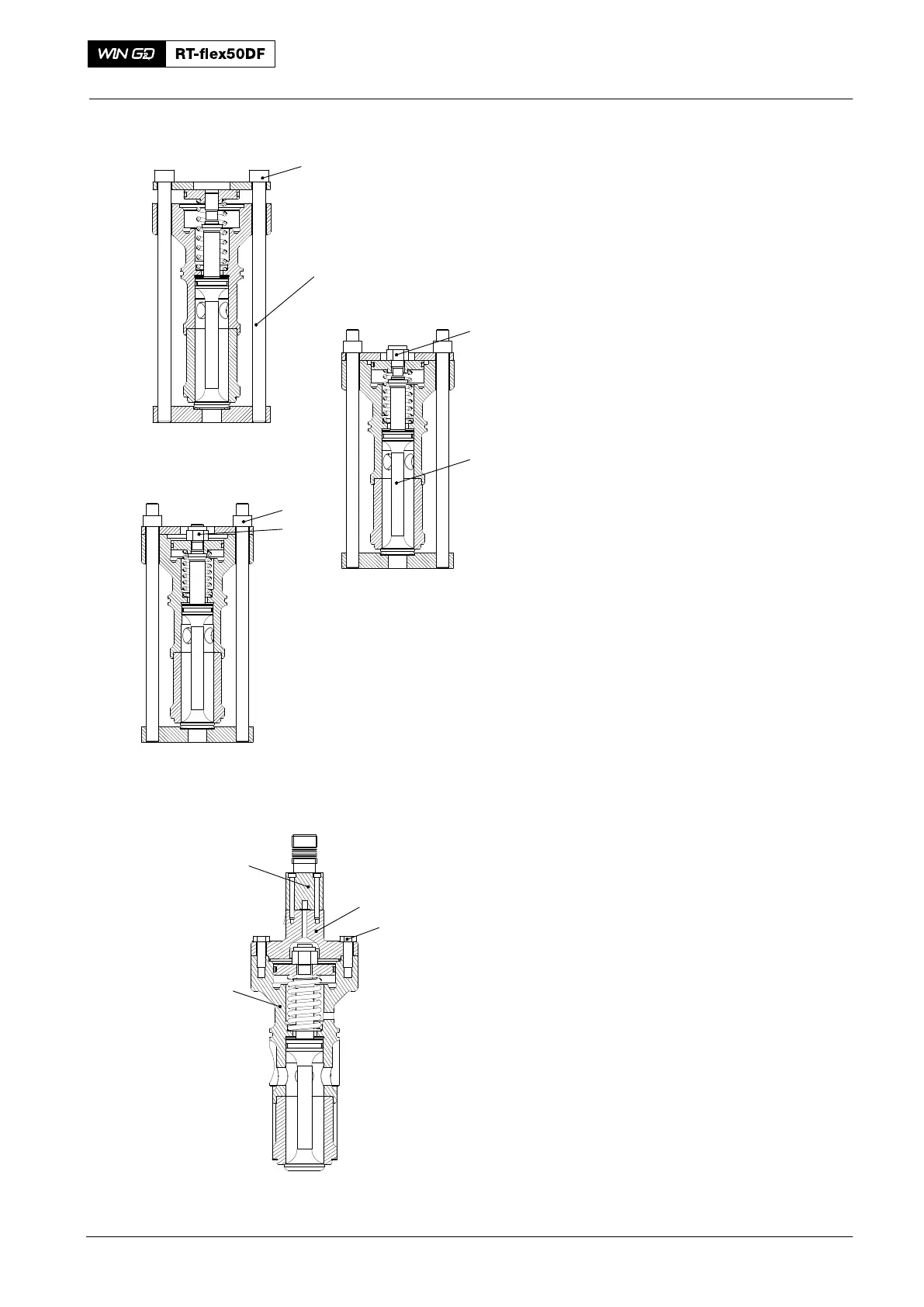
9) Put the tool (94281, Fig. 7) in position
on the housing.
10) Tighten equally the two nuts (1) until
you get to the second position.
Note: Do not get Molykote paste G on
the thread of the valve spindle (3)
where the insert of the self-locking
nut (2) will go.
11) Apply a thin layer of Molykote paste G
to the thread of the valve spindle (3).
12) Attach the self-locking nut (2) to the
valve spindle (3). Do not torque the
self-locking nut at this step.
13) Fully tighten equally the two nuts (1) of
the assembly tool (94412A).
14) Torque the self-locking nut to 140 Nm.
15) Remove the tool (94281).
16) Tap the top of the valve spindle (7) with
a hammer. The valve spindle must
spring back to its initial position.
17) Attach the cover (1, Fig. 8) together
with the solenoid valve (4) to the
housing (3) with the two screws (2).
18) Torque the the M12x35 two screws (2)
to the value given in 0352−2.
2016
Starting Air Valve: Removal, Disassemble, Grinding, Assemble, Installation
94281
Initial Position
1
WCH03192
Second Position
2
3
Fully Tightened Position
1
2
Fig. 7
4
2
1
WCH03192
3
Fig. 8