Maintenance
3603−1/A1
Winterthur Gas & Diesel Ltd.
3/ 3
3. Installation
1) Operate the turning gear to move the
applicable crank to BDC.
2) If necessary, remove the flange
(94337B, Fig. 3) from the inlet
pipe (11).
3) Attach the lifting tool (94337, Fig. 1) to
the inner pipe and the engine room
crane (3).
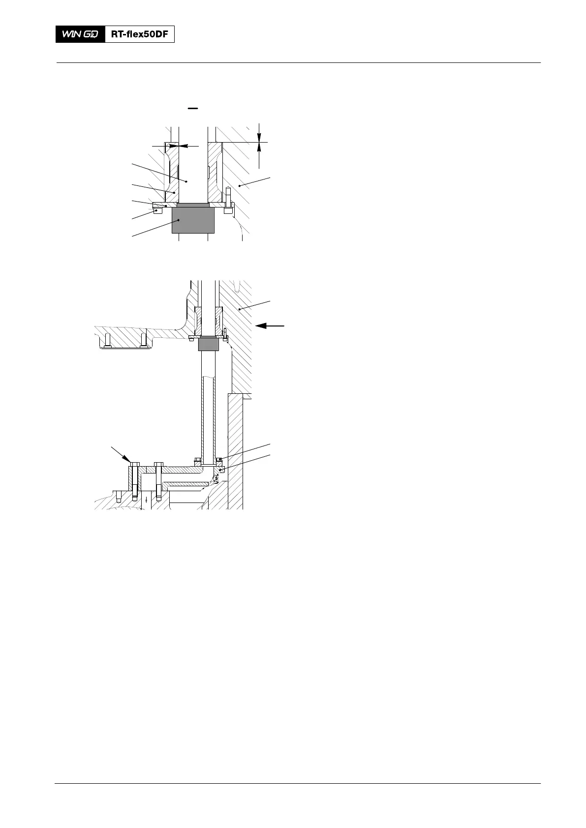
4) Push the ring holder (6, Fig. 4) and
sleeve (7) over the inner pipe (8).
5) Attach carefully the inner pipe (8) in the
connection piece (3). Hold the inner
pipe in position with the screws (2). Do
not tighten the screws at this step.
6) Operate the turning gear to carefully
move the crank approximately 30_ after
TDC.
7) Push the ring holder (6) and the sleeve
(7) into the bore of the cylinder
block (1). Hold the ring holder and the
sleeve with the screws (5). Do not
tighten the screws at this step.
8) Lightly tighten the screws (2, 5). Make
sure that you can move the inner
pipe (8) and the ring holder (6).
9) Use the centering piece (94337A) to
align the ring holder (6) and the inner
pipe (8) until you get the clearance A is
0.30 mm to 0.39 mm.
10) Tighten the screws (2, 5). Make sure
that there is a clearance B is between
0.08 mm to 0.20 mm as shown. Also,
do the check again to make sure that
the clearance A is 0.30 to 0.39 mm.
11) Install the oil inlet pipe 1 (Fig. 1).
2016
Piston Cooling and Crosshead Lubrication: Removal and Installation of Inside Pipe
013.418/05
I
Fig. 4
2
3
4
013.419/05
94337A
I
1
8
7
6
5
1
A
B