Maintenance5552−2/A1
Winterthur Gas & Diesel Ltd.
2/ 8
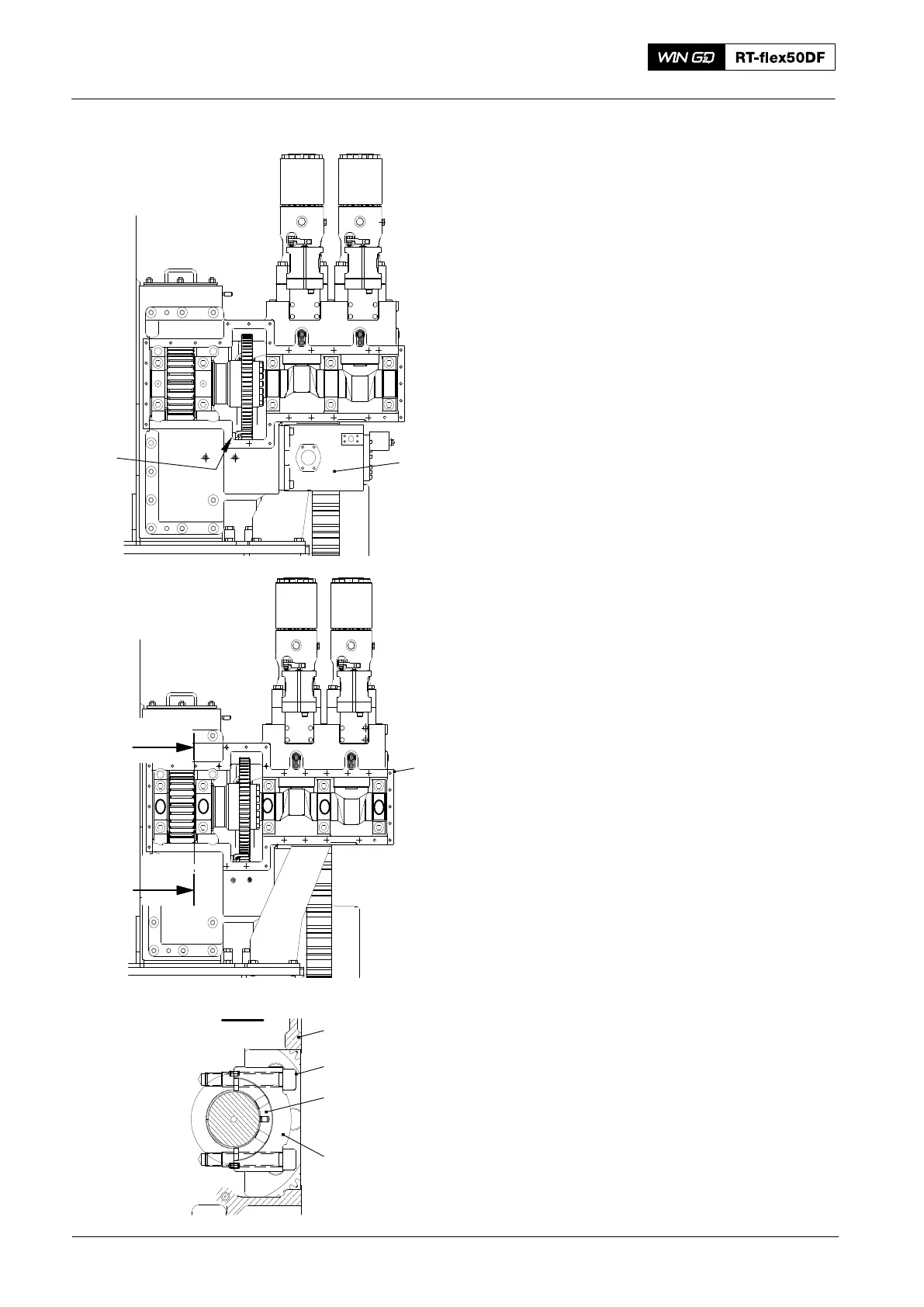
5) Remove the servo oil pump (1, Fig. 2)
and the nozzle (2), refer to 5552−1.
6) Make sure that the bearing covers at
positions No. 2, No 3 and No. 4 (Fig. 3)
and the housing (1), have marks to
identify them as a set.
Note: The bearing at position No. 2 has
the two thrust bearing ring
halves (3).
2016
Supply Unit: Removal and Fitting of Camshaft and Bearing Shells
012.980/05
Fig. 2
1
2
I - I
012.981/05
1
1
2
3
4
5
4
3
2
1
Fig. 3
I
I