Maintenance5552−2/A1
Winterthur Gas & Diesel Ltd.
8/ 8
7. Completion
1) Make sure that the radial and axial
clearances are in the limits given in
refer to 0330−1, Supply unit.
2) If the axial clearances are not in the
specified range, loosen the screws on
one of the bearing covers, Fig. 8.
3) Make sure that the dowel pin (6) is in
the bearing cover (7).
4) Put the bearing cover in position and
torque the screw again (refer to
paragraph 4, step 10) to step 14).
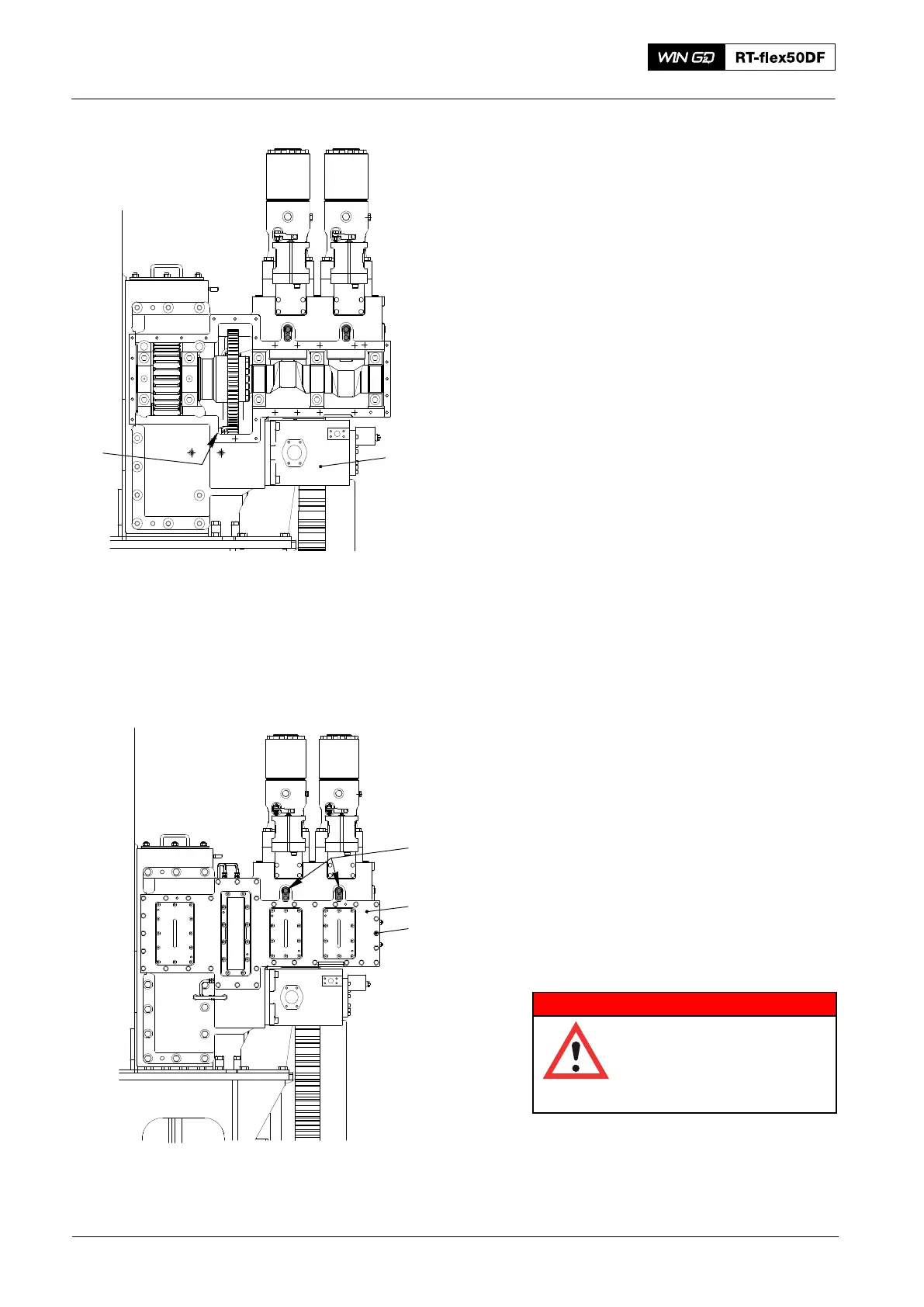
5) Install the nozzle (2, Fig. 11) and the
servo oil pump (1), refer to 5552−1
paragraph 4.2 and paragraph 5.
6) Apply sealing compound to the sealing
surfaces of the cover (1, Fig. 12).
7) Attach the cover (1) to the casing with
the screws (2).
8) Cut in the fuel pumps and remove tools
94430, refer to the procedure given in
the Operation Manual 5556−2.
9) Set to on the oil pump.
WARNING
Injury Hazard: Before you
operate the turning gear,
make sure that no
personnel are near the
flywheel, or in the engine.
10) Operate the turning gear to turn the
engine.
11) Make sure that lubricating oil flows to
all lubricating points and bearings.
Supply Unit: Removal and Fitting of Camshaft and Bearing Shells
2016
012.979/05
94430
1
2
Fig. 11
Fig. 12
012.980/05
1
2