Maintenance
5552−2/A1
Winterthur Gas & Diesel Ltd.
7/ 8
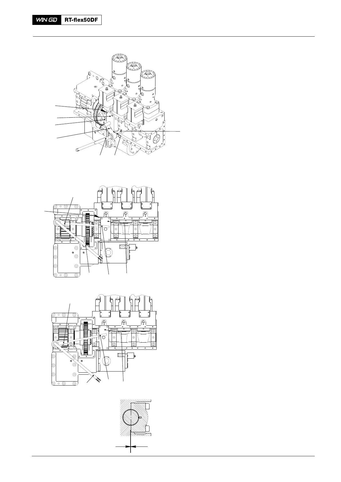
6. Bearing Covers −
Installation
Note: The position of the torque
amplifier in Fig. 9 is for reference.
Start the procedure to tighten the
screws (1) at bearing No. 1.
1) Attach the limiter (94566C) with the
screws (6) (from the cover) to the
housing below fuel pump No. 1.
2) Put the screwdriver bit (2) on to the
screw (1).
3) Attach the torque amplifier (4) and the
applicable extension (5) to the
screwdriver bit (2) in the position
shown.
Note: The ratio between the torque
wrench (3) and the torque amplifier
(4) is 1:5.
4) Torque the screw (1) as follows:
a) Adjust the torque wrench (3) to
290 Nm. The torque value for the
screws (1) is 1450 Nm.
b) Put the torque wrench (3) on the
torque amplifier (4).
c) Torque the screw (1) to the value
of 290 Nm on the torque
amplifier (4).
5) Make sure that there is no clearance
at X (Fig. 10).
6) Do step 7) to step 13) for the bottom
screw of bearing No. 1.
7) Do step 10) to step 13) for the
remaining screws (1) of the bearing
covers.
Supply Unit: Removal and Fitting of Camshaft and Bearing Shells
2016
94566C
C
BEARING COVER NO. 1
4
3
5
Fig. 9
013.067/05
6
94566C
013.067/05
1
23
6
5
4
94566C
3
5
4
X
Fig. 10