Maintenance6606−1/A1
Winterthur Gas & Diesel Ltd.
2/ 7
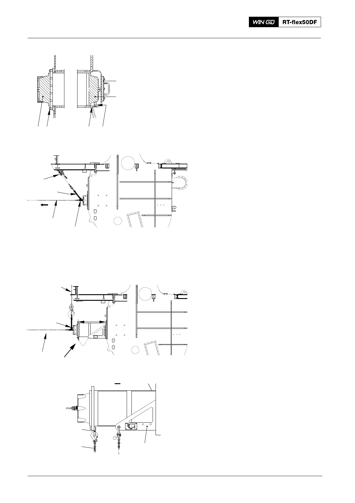
2. Removal
1) Remove the screws (4, Fig. 2)11 on the
fixed side.
2) Remove the cover (1) on the expansion
side.
3) Attach the three swivel lugs
(94048−M16) to the front of the SAC.
4) Attach the left and the right supports
(94663A, 94663B) to the receiver with
its four screws (each).
5) Tighten the screws on the supports
(94663A, 94663B).
6) Attach the chain (94666I) to the outer
swivel lugs (94048−M16) in the front of
the SAC.
7) Attach the manual ratchet (H1) to the
beam and the chain (94666I).
8) Attach the manual ratchet (H3) to an
applicable strong-point in the engine
room and the center swivel lug
(94048−M16) in the cover (5).
9) Operate the manual ratchet (H1) to get
sufficient tension to hold the mass of
the SAC.
Note: During step 10) operate the manual
ratchet (H1) to keep tension on the
chain.
10) Operate the manual ratchet (H3) to pull
the SAC approximately 750 mm from
the receiver.
11) Attach the two lugs (94663C, Fig. 3) to
the SAC.
12) Attach the two safety chains (94663D)
to the lugs.
13) Operate the manual ratchet (H3) to
carefully move the SAC from the
platform area to below the engine room
crane.
14) Attach the engine room crane to the
chain (94666I).
15) Remove the manual ratchet (H1) from
the chain (94666I).
16) Remove the manual ratchet (H3) from
the middle swivel lug (94048−M16).
17) Remove the applicable bottom plates
and rails from the platform. This lets
you move the SAC through the platform
during a later step.
2016
Scavenge Air Cooler: Removal and Installation
EXPANSION
SIDE
STEP
FIXED
SIDE
H3
H1
94048−M16
94666I
WCH03084
2
1
3
45
Fig. 2
I
Engine Room
Crane
H3
94666I
Fig. 3
750 mm
I
94663A
94663B
94663C
94663D