Maintenance8447−1/A1
Winterthur Gas & Diesel Ltd.
2/ 5
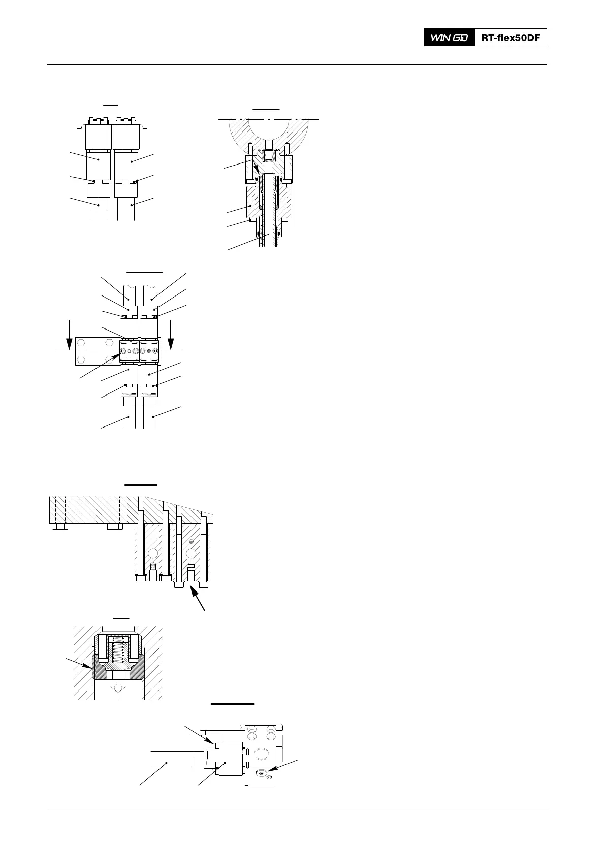
6) On the flange (1, Fig. 2), loosen the
screws (2).
7) Push down the flange (1) to get air in
the HP servo oil pipe (3).
8) On the flange (7), loosen the
screws (8).
9) Push up the flange (7) to let the servo
oil drain from the HP oil pipe (3).
10) On the flange (9) loosen the
screws (10).
11) Push down the flange (9) to get air into
the servo oil pipe (11).
12) Loosen the screw plug (19) to drain the
oil from the HP servo oil pipe (11).
13) On the flange (6), loosen the screws
(5).
14) Push down the flange (6) to get air in
the servo ol pipe (4).
15) Loosen the screw plug (19) to drain the
HP servo oil pipe (12).
2. Removal
2.1 HP Servo Oil Pipes (11, 12)
1) Remove the screws (21) from the
flange (20).
2) Move the flange (20) away from the
servo oil pump.
3) Remove the screws (10) from the
flange (9).
4) Push down the flange (9).
5) Carefully remove the HP servo oil
pipe (11).
6) Remove the non-return valve (22).
7) Apply protection to the sealing
faces (SF) to prevent damage.
2.2 HP Servo Oil Pipes (3, 4)
1) Remove the screws (2, 5) from the
flange (1, 6).
2) Push down the flange (1, 6).
3) Remove the screws (15), then remove
the intermediate piece (16).
4) Remove the screws (8, 17).
5) Push the flange (7, 18) up.
2016
HP Servo Oil Pipe: Removal, Grind, Installation
SF
1
2
3
I - I
II - II
8
VV
22
3
III - III
9
12
15
21
20
19
4
10
14
13
11
1
2
3
4
5
6
18
17
11 or 12
16
WCH02974
WCH02974
WCH02974
WCH02974
Fig. 2
VI
V - V
IV
7
VI