Maintenance
8447−1/A1
Winterthur Gas & Diesel Ltd.
5/ 5
5. Installation
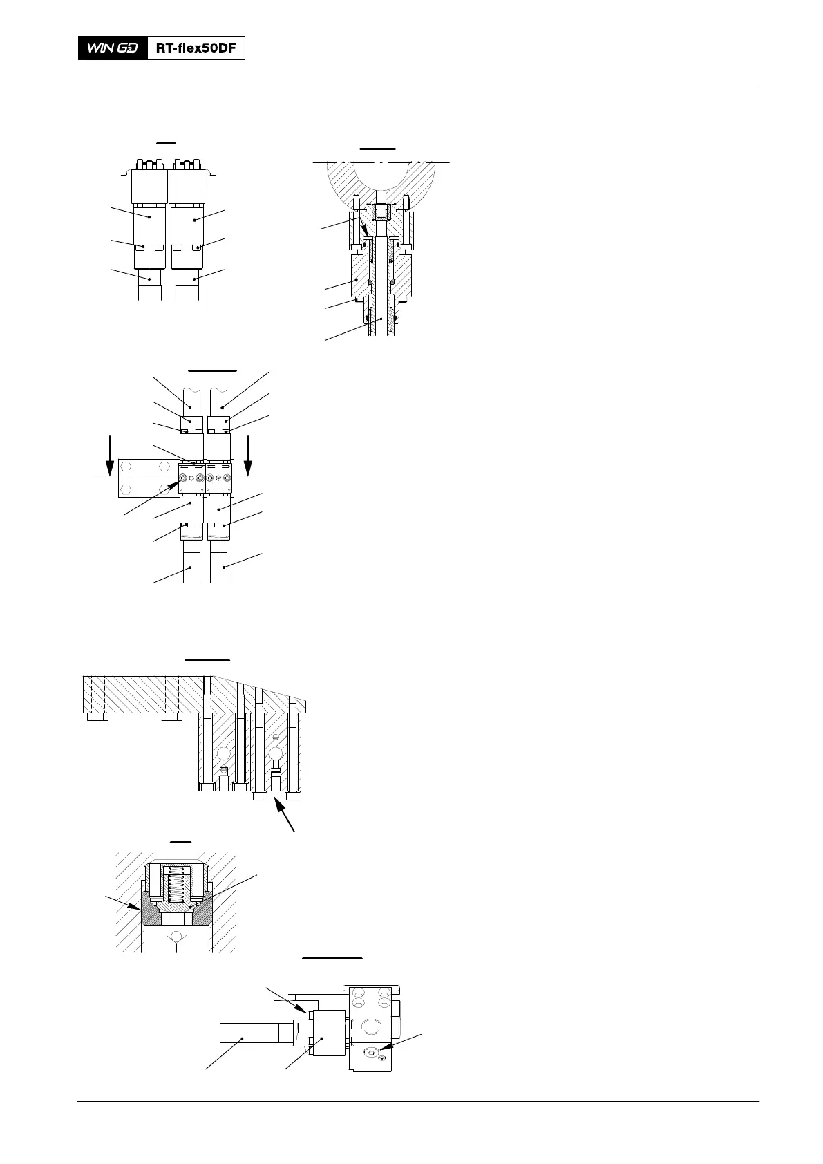
5.1 HP Servo Oil Pipes (11, 12)
1) Remove all of the protection from:
D The sealing faces (SF) in the valve
housing (22, Fig. 5) and the HP servo
oil pipes (11, 12)
D The intermediate piece (16)
D The servo oil pump.
2) Apply oil to the the threads of all the
screws (2, 5, 8, 10, 13, 17, 21).
3) Attach the intermediate piece (16) to
the flat bar with the screws (15). Do not
tighten the screws at this step.
4) Put the non-return valve (23) in the
correct position.
5) Torque the non-return valve (23) to
40 Nm.
6) Carefully put the HP servo oil pipe (11,
12) in the intermediate piece (16).
Make sure that the pipe (11) that has
the non-return valve (23) is in the
correct position.
7) Torque symmetrically the eight screws
(21) (four screws for each HP servo oil
pipe) to 40 Nm.
8) Torque symmetrically the four screws
(10) and the four screws (13) to 40 Nm.
5.2 HP Servo Oil Pipes (3, 4)
1) Remove the protection from the sealing
faces (SF) of the HP servo
oil pipes (3, 4).
2) Carefully put the HP servo oil pipes (3,
4) in position in the intermediate piece
(16) and the valve housing.
3) Torque symmetrically the screws (8,
17) to 40 Nm.
4) Torque symmetrically the screws (2, 5)
to 40 Nm.
5) Tighten the screws (15) on the
intermediate piece (16).
6) Tighten the screw plug (19).
7) Install the stirrup bolts (3, Fig. 1).
2016
HP Servo Oil Pipe: Removal, Grind, Installation
SF
1
2
3
I - I
II - II
8
VV
22
3
III - III
9
12
15
21
20
19
4
10
14
13
11
1
2
3
4
5
6
18
17
11 or 12
16
WCH02974
WCH02974
WCH02974
WCH02974
VI
V - V
IV
7
VI
Fig. 5
23