APPENDIX B TYPICAL SYSTEM DIAGRAMS
445-0089-01-01
103
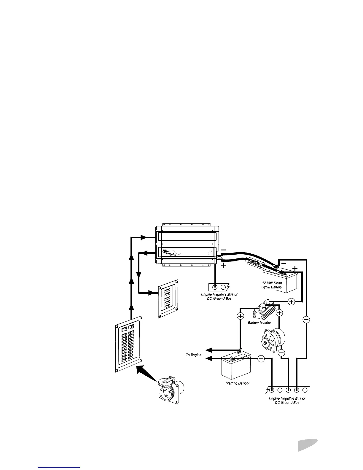
Marine System
Figure 23 illustrates a typical marine system with the following components:
1. AC power supplied from a shorepower connector
2. An AC source panel that includes a Max 30A circuit breaker that supplies
the inverter•charger
3. An AC load panel with branch circuit breakers that supply only loads that
run off the inverter•charger
4. Engine negative bus or DC ground bus
5. DC power supplied by a battery bank and protected by a DC fuse in the
positive cable
6. Battery isolator
7. DC alternator
8. Starting battery
See the Note on page 101 for information about the ABYC Warning label that
must be used in marine installations.
Figure 23 Typical Marine System
DC Fuse /
disconnect or
circuit breaker
AC Load Panel
AC Source Panel
Shorepower
 Loading...