PROSINE 2.0 INVERTER•CHARGER USER’S MANUAL
10
445-0089-01-01
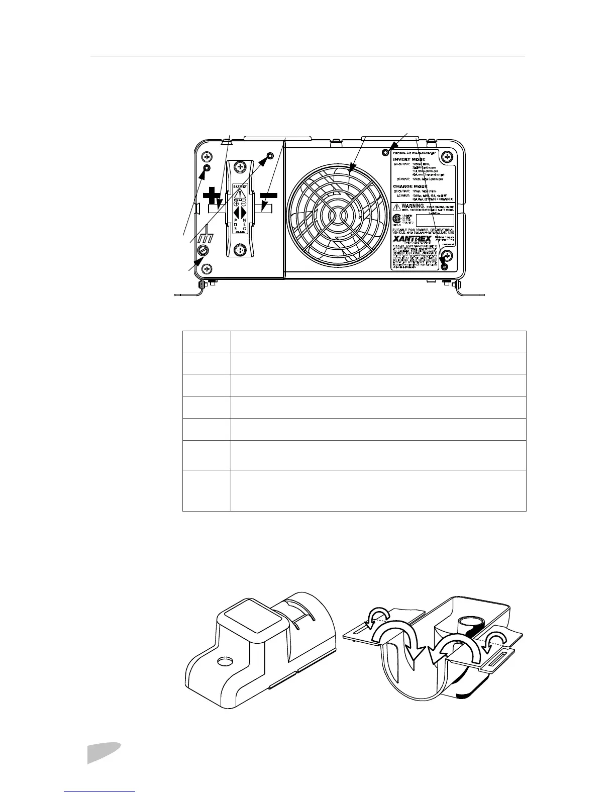
Inverter•Charger: DC End
Figure 4 Inverter•Charger: DC End
DC Terminal Covers
Two covers—red for positive and black for negative—are supplied to prevent
accidental contact with the cabling connectors after installation.
Figure 5 DC Terminal Cover: Top View on Left; Bottom View on Right
c
d
e
f
g
h
B
Feature Description
c
Positive DC cabling terminal
d
Negative DC cabling terminal
e
Cooling fan. (For details, see
“Fan Operation‚” on page 63
.)
f
Screw holes for mounting accessory modules
g
Chassis ground lug. Provides a ground path for the inverter•charger
chassis to the DC system ground.
h
Screw holes for mounting the optional DC wiring enclosure. See
“Materials List‚” on page xviii
for information about the crimp-on
ring terminals to be used with this option.
 Loading...