PROSINE 2.0 INVERTER•CHARGER USER’S MANUAL
36
445-0089-01-01
2. Switch off all devices operating from the battery, or open the battery
switch, if present, to disconnect the battery.
3. If the charger has been operating, wait ten minutes for any explosive
battery gasses to dissipate.
4. Remove the nut that secures the existing negative DC wire to the battery.
5. Move or reorient the existing negative DC wire so there is a flat surface
on which to seat the battery temperature sensor mounting plate. You may
need to bend the ring terminal and/or wires downward to allow the sensor
to seat on the top surface of the upper ring terminal.
6. Mount the sensor directly on top of the negative DC wire terminal, as
shown in Figure 16, and tighten the terminal nut firmly.
7. Check that the sensor and all wires are fastened securely.
8. Turn the battery switch on again (if you opened it in step 2).
9. Route the sensor cable to the inverter•charger and plug it into the
BATTERY TEMP
jack. Secure the cable along its length.
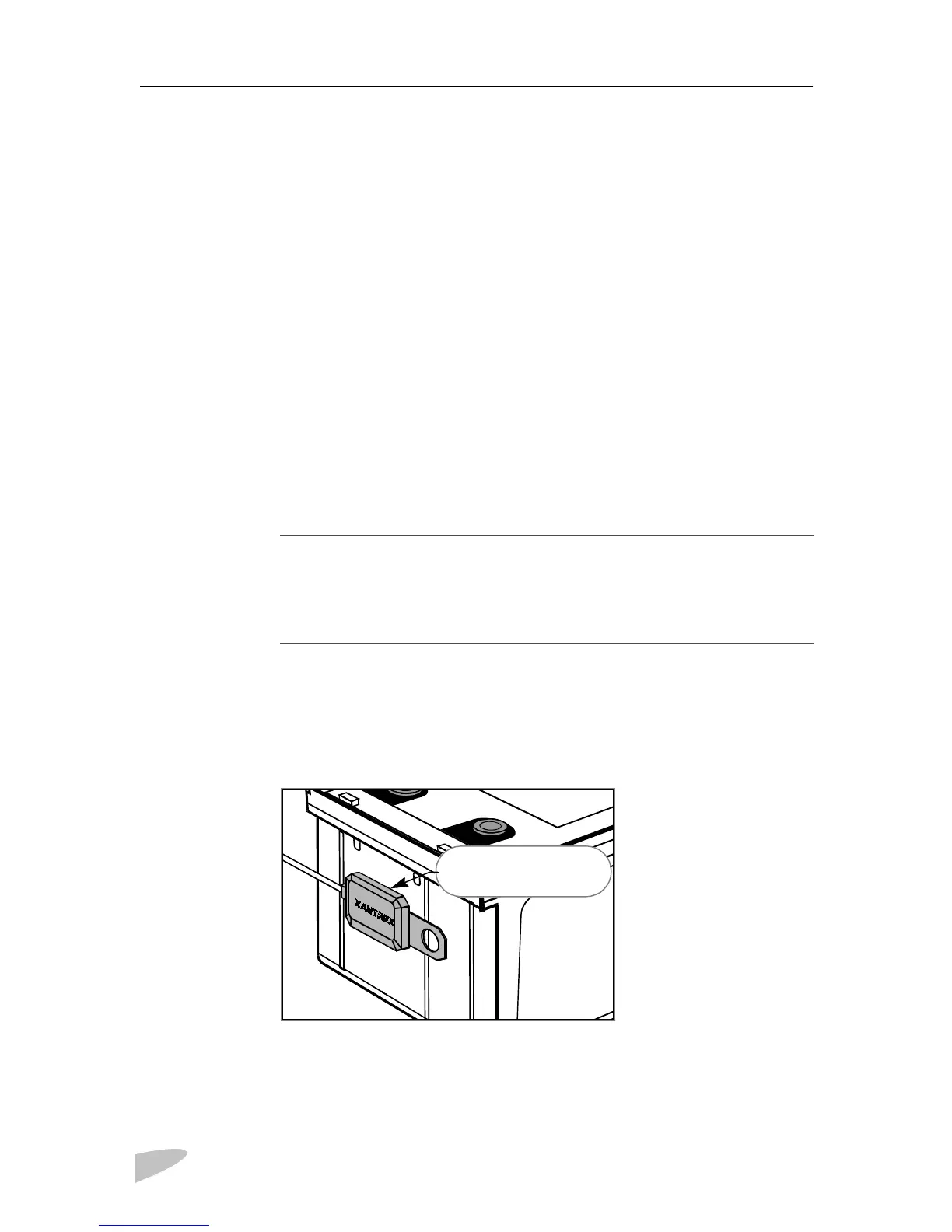
Mounting to the Side of the Battery Case
➢
➢➢
➢
To mount the sensor on the battery case
See Figure 17.
Figure 17 BTS Attached to Battery Case
1. Select the battery to be monitored (see step 1 in the preceding procedure).
2. Select a side suitable for attaching the sensor.
NOTE
In this procedure, you must install the DC wire on the battery terminal first. Then
the sensor is installed on top of the DC wire. This sequence is required to provide
the best connection to the battery and to thereby ensure correct performance of the
sensor.
Adhesive backing allows
for easy mounting on side
of battery.
 Loading...