PROSINE 2.0 INVERTER•CHARGER USER’S MANUAL
8
445-0089-01-01
INVERTER•CHARGER FEATURES
Inverter•Charger: AC End
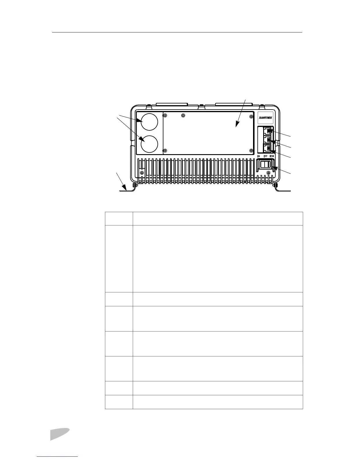
Figure 2 AC End View (Blank Panel Option)
Temperature
c
d
e
f
h
i
DISPLAY
BATTERY SYNC
TEMP
Feature Description
c
ON/OFF/REM Switch:
ON:
Normal operation according to the way the unit has been
configured via the display panel.
OFF:
The inverter and charger are off; shorepower is not passed
through to the loads. The unit draws the lowest battery current
possible (less than 2mA).
REM:
With the switch in this position, the unit can be turned on
and off remotely. (For details, see
“ON/OFF/REMote Control of
Inverter•Charger Operation‚” on page 63
.)
d
DISPLAY:
Jack for the display panel.
e
BATTERY TEMP/REMOTE:
Jack for the battery temperature
sensor. Also provides a connection for remote shutdown. See
“Step
10: Connecting the Remote Shutdown‚” on page 38
.
f
SYNC:
Jack for synchronizing a second PROsine 2.0
Inverter•Charger to produce 120/240V split phase AC. For details,
see
Section 7: “Series Operation”
starting on
page 83
.
g
Removable panel. The blank panel option is shown. For details, see
“AC Panel Options‚” on page 9
. The AC wiring compartment is
located behind the panel.
h
Knockouts for AC wiring
i
Mounting flange
 Loading...