PROSINE 2.0 INVERTER•CHARGER USER’S MANUAL
24
445-0089-01-01
Step 3: Mounting the Inverter•Charger
➢
➢➢
➢
To mount the PROsine Inverter•Charger
1. Remove the inverter•charger from its shipping container, verify that all
components are present, and record relevant product information on
page xviii.
2. Turn off the ON/OFF/REM switch on the AC end.
3. Select an appropriate mounting location and orientation.
(See
Figure 9
.)
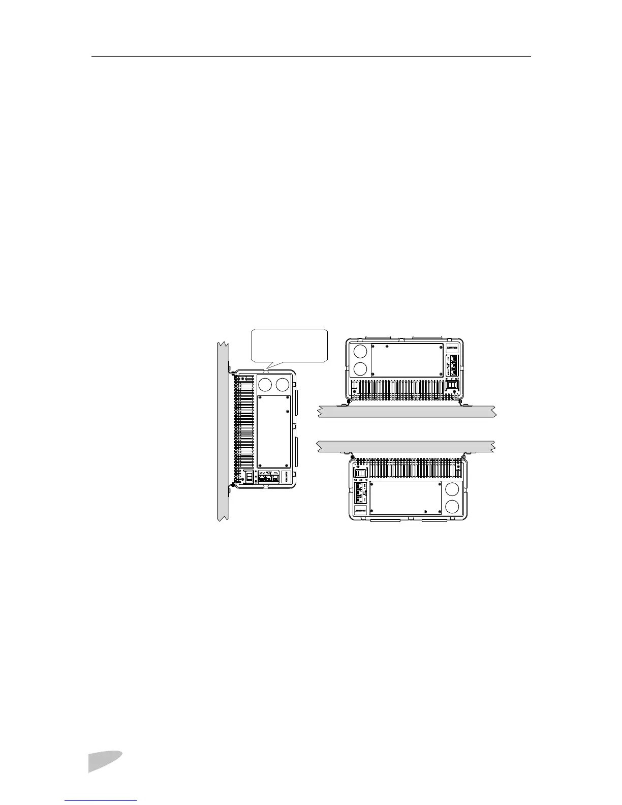
To meet regulatory requirements, the PROsine must be mounted in one of
the following orientations:
• In a horizontal position on a vertical surface with the AC knockouts at
the top as shown in Figure 9
.
• On a horizontal surface with the DC terminals on the low side
• Under a horizontal surface
Figure 9 Approved Mounting Orientations
4. The
PROsine 2.0 Quick Installation Guide
has a mounting template
printed on it. Tape it to the mounting surface and pilot-drill the desired
number of mounting holes. Remove the template.
5. Fasten the inverter•charger to the mounting surface. If you are mounting
the unit on a wall or bulkhead, use #12 or #14 pan-head wood or sheet
metal screws to secure it to the framing behind the wall or bulkhead.
Alternatively, use nut inserts and 1/4-20 machine screws.
Side with AC
knockouts
must be up.
 Loading...