SECTION 3 INSTALLATION
445-0089-01-01
31
Step 7: Connecting the DC Cables
Follow the procedure given below to connect the battery leads to the terminals
on the DC end. The cables should be as short as possible and large enough to
handle the required current, in accordance with the electrical codes or
regulations applicable to your installation. Table 2 on page 21 specifies the
minimum DC cable size and maximum fuse size for the PROsine 2.0.
Do not route your DC cables through an electrical distribution panel, battery
isolator, or other device that will cause additional voltage drops.
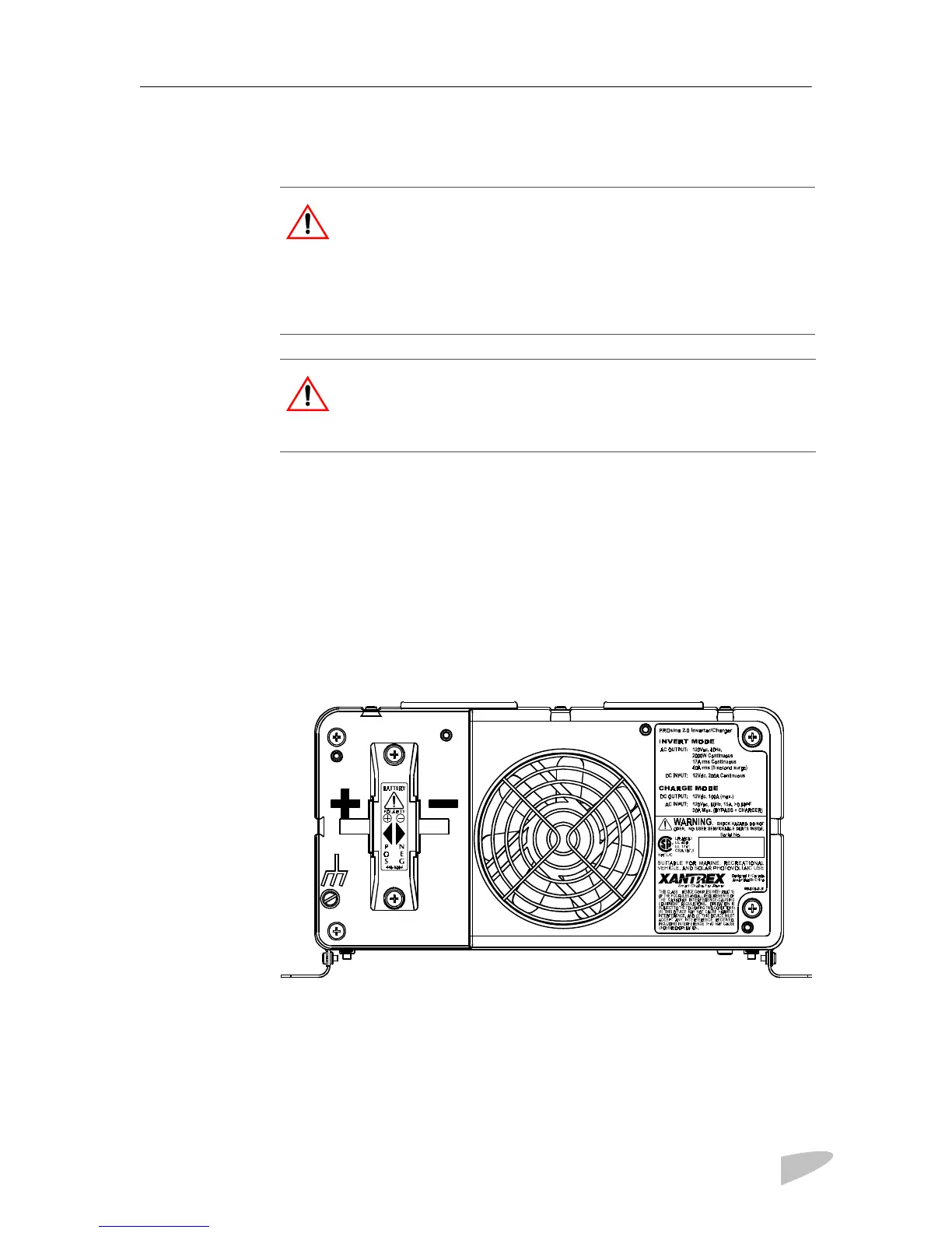
Figure 14 shows the DC end for your reference.
Figure 14 DC End
CAUTION
Before making the final DC connection, check cable polarity at both the
battery and the inverter•charger. Positive must be connected to positive;
negative must be connected to negative.
Reversing the positive and negative battery cables will damage the
inverter•charger and void your warranty. This type of damage is easily
detected.
WARNING: Fire Hazard
Use only copper wire rated 75°C minimum. Make sure all DC
connections are tight to a torque of 216–240 inch-pounds (24–27Nm).
Loose connections will overheat.
B
 Loading...