SECTION 2 PRODUCT ORIENTATION
445-0089-01-01
11
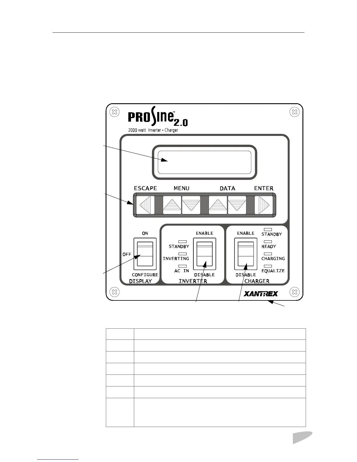
DISPLAY PANEL FEATURES
The display panel lets you monitor and control the PROsine 2.0 system. For
convenience, the liquid crystal display (LCD) is backlit and the panel can be
configured so an audible tone alerts you to any warnings or system faults that
occur. The panel’s features are described below.
Figure 6 PROsine 2.0 Inverter•Charger Display Panel
c
d
e
h
g
f
Feature Description
c
DISPLAY mode switch
d
INVERTER switch and status LEDs
e
CHARGER switch and status LEDs
Menu navigation and data selection buttons
LCD display
Two input jacks (not illustrated) on the bottom of the unit behind the
faceplate. Either jack can be used for the communication cable that
connects the panel to the inverter•charger. The second jack can be
used to connect future accessories.
 Loading...