PROSINE 2.0 INVERTER•CHARGER USER’S MANUAL
30
445-0089-01-01
Connections for Single Hardwire Output With GFCI
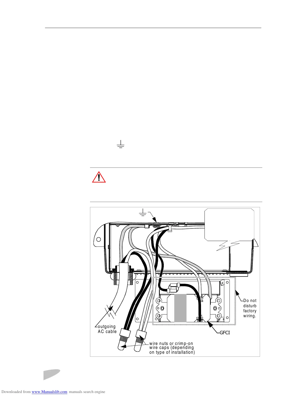
Figure 13 is a cutaway top view of the PROsine 2.0 wiring compartment
showing one set of outgoing AC wires with the GFCI option.
➢
➢➢
➢
To make the AC output wiring connections
1. Run 10AWG 2-conductor-plus-ground through one of the cable clamps
on the AC end.
2. Strip about two inches of the jacket from the AC cable and separate the
wires. Strip insulation from each of the wires according to the guidelines
given by the connector manufacturer.
3. Connect the outgoing black and white (line and neutral) AC wires to the
PROsine black and white AC output wires.
4. Connect the outgoing ground wire to the chassis using one of the screws
marked .
5. Tuck the wires into the left-hand side of the wiring compartment so they
don’t interfere with the GFCI assembly.
Figure 13 Single Hardwire Output With GFCI
WARNING: Shock Hazard
If you are not using the hardwire output circuit, you must cap off its line
and neutral wires.
Use twist-on wire nuts where allowed; use crimp-on wire caps in other
applications.
grounding screw
Cutaway view of
PROsine 2.0 wiring
compartment as
seen from the top.
Do not
disturb
factory
wiring.
GFCI
wire nuts or crimp-on
wire caps (depending
on type of installation)
outgoing
AC cable
 Loading...