445-0089-01-01
xiii
List of Figures
Fig Title
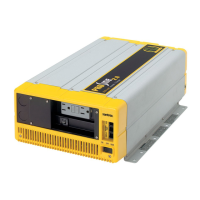
1 PROsine 2.0 Materials as Shipped . . . . . . . . . . . . . . . . . . . . . . . . . . . . . xix
2 AC End View (Blank Panel Option) . . . . . . . . . . . . . . . . . . . . . . . . . . . . 8
3 Panel Equipped With GFCI and Circuit Protector . . . . . . . . . . . . . . . . . 9
4 Inverter•Charger: DC End. . . . . . . . . . . . . . . . . . . . . . . . . . . . . . . . . . . . 10
5 DC Terminal Cover: Top View on Left; Bottom View on Right . . . . . . 10
6 PROsine 2.0 Inverter•Charger Display Panel . . . . . . . . . . . . . . . . . . . . . 11
7 Battery Temperature Sensor . . . . . . . . . . . . . . . . . . . . . . . . . . . . . . . . . . 16
8 Typical Recreational Vehicle and Fleet Vehicle Installation . . . . . . . . . 19
9 Approved Mounting Orientations . . . . . . . . . . . . . . . . . . . . . . . . . . . . . . 24
10 Interior of AC Wiring Compartment. . . . . . . . . . . . . . . . . . . . . . . . . . . . 25
11 Incoming AC Cable (Top, cutaway view of wiring compartment). . . . . 26
12 Hardwire AC Output Option (Top, cutaway view of wiring compartment) 29
13 Single Hardwire Output With GFCI . . . . . . . . . . . . . . . . . . . . . . . . . . . . 30
14 DC End . . . . . . . . . . . . . . . . . . . . . . . . . . . . . . . . . . . . . . . . . . . . . . . . . . 31
15 DC Cable Connections . . . . . . . . . . . . . . . . . . . . . . . . . . . . . . . . . . . . . . 33
16 BTS Attached to Negative Battery Terminal . . . . . . . . . . . . . . . . . . . . . 35
17 BTS Attached to Battery Case. . . . . . . . . . . . . . . . . . . . . . . . . . . . . . . . . 36
18 Cabling Details for Remote Shutdown Feature. . . . . . . . . . . . . . . . . . . . 39
19 Schematic for Remote Shutdown Feature. . . . . . . . . . . . . . . . . . . . . . . . 39
20 Two Inverter•Charger Series Operation System . . . . . . . . . . . . . . . . . . . 85
21 Inverter•Charger Dimensions . . . . . . . . . . . . . . . . . . . . . . . . . . . . . . . . . 100
22 Residential Backup System . . . . . . . . . . . . . . . . . . . . . . . . . . . . . . . . . . . 102
23 Typical Marine System . . . . . . . . . . . . . . . . . . . . . . . . . . . . . . . . . . . . . . 103
24 Batteries Connected in Parallel . . . . . . . . . . . . . . . . . . . . . . . . . . . . . . . . 116
25 Batteries Connected in Series . . . . . . . . . . . . . . . . . . . . . . . . . . . . . . . . . 117
26 Series–Parallel and Cross-Tied Connections . . . . . . . . . . . . . . . . . . . . . 118
27 Three-Stage Charging Profile . . . . . . . . . . . . . . . . . . . . . . . . . . . . . . . . . 120
 Loading...


