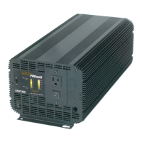
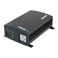
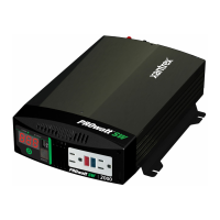
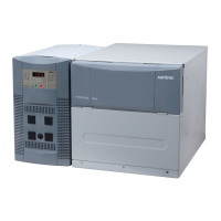
PROSINE 2.0 INVERTER•CHARGER USER’S MANUAL
20
445-0089-01-01
Generator
When a generator or any other secondary AC power source is
included, a manual or automatic
AC source selector switch
must be installed
ahead of the circuit breaker in the line leading to the inverter•charger.
AC Disconnect and Over-Current Protection Device
To meet CSA, UL,
and electrical code requirements, the inverter•charger’s AC and DC inputs and
outputs must be provided with over-current protection (such as a circuit
breaker or fuse) and a disconnect device, as follows:
AC Input:
The circuit breaker or fuse used to protect the PROsine 2.0
Inverter•Charger must be rated no more than 30A and must be approved
for use on 120Vac branch circuits. The wire used between the breaker and
the inverter•charger input must be sized to match the circuit breaker, in
accordance with the electrical codes or regulations applicable to your
installation. The “AC Service Rating” setting of the inverter•charger must
also be set to match the size of the breaker provided. (See Section 4:
“Configuration” on page 41 and following.)
AC Output:
The circuit breaker or fuse must be rated at no more than
30A and must be approved for use on 120Vac branch circuits. The wire
used between the inverter•charger and the AC output breaker must be
sized to match the AC input circuit breaker’s rating. The wire from the
AC output breaker to your loads must be matched to the rating of the AC
output breakers.
Disconnect Devices:
Each system requires a method of disconnecting
the AC circuits. If the over-current protection device is a circuit breaker, it
will also serve as the disconnect. If fuses are used, separate AC
disconnect switches will be needed ahead of the fuses.
AC Distribution Panels
Most systems incorporate distribution centers both
ahead of the inverter•charger (the AC source panel) and between the
inverter•charger and the loads (the AC load panel). A source panel includes a
main circuit breaker, which serves as over-current protection and as a
disconnect for the AC shorepower supply line. Additional circuit breakers
serve individual circuits, one of which serves the inverter•charger. The AC
load panel can incorporate both the main 30A AC output circuit breaker and
breakers for individual load circuits.
NOTE
Do not connect the output of a single PROsine 2.0 to what is known as a “multi-
wire branch circuit”. These are 4-wire circuits consisting of a ground, neutral, and
two lines that are 180 degrees out of phase with each other (from a standard 120/
240V “split phase” circuit). These circuits are commonly used in kitchens to
power “split receptacles” where the top and bottom halves of a duplex receptacle
are connected to different lines. If you need to run multi-wire branch circuits from
your inverter system, you will need to use two PROsine 2.0 Inverter•Chargers in a
series system to create 120/240Vac split-phase power. For details, see
Section 7:
“Series Operation”
. For more information about multi-wire branch circuits, refer
to the US National Electrical Code (NFPA 70, 1999) para 210–4 and the Canadian
Electrical Code (CSA C22.1-1998) section 26–710.
 Loading...


